Search the Community
Showing results for tags 'Tutorial'.
-
Te vas al disco C y creas una carpeta llamada 0ADSVN. @Obskiuras Sección 2: Haciendo tu primer “Checkout” Ahora necesitamos verificar la URL y hacer un “checkout” de la actual SVN en el directorio principal de tu disco duro. El acceso para anónimos es: http://svn.wildfiregames.com/public/ps/trunk Pero ahora la nueva versión SVN es llamada nighly build, que se actualiza en la madrugada europea. https://svn.wildfiregames.com/nightly-build/trunk Usa el directorio que prefieras. Aunque sugiero usar la carpeta C:ADsvn Trata de no usar carpetas con espacios tales como:, C:Mis DocumentosAD puede causar problemas. Ahora, sigue estos pasos. Haz “checkout” en el directorio del SVN. 1 en Windows Explorer, navega al directorio que has elegido para usar como Directorio raíz SVN. 2 Click derecho. Selecciona 'Checkout...' en la parte del SVN: 3 pon la 'Url del repositorio'. Y deja lo demas igual:
-
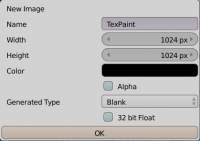
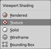
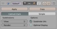
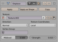
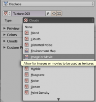
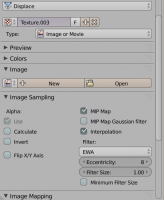
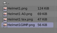
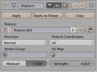
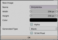
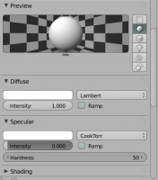
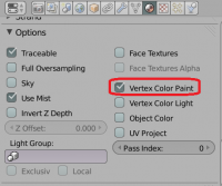
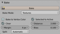
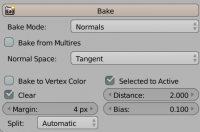
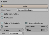
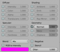
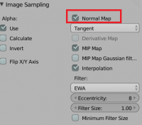
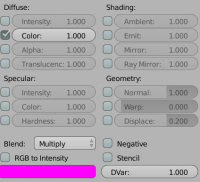
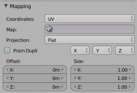
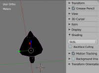
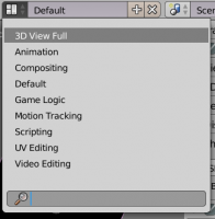
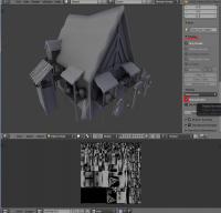
Disclaimer : This is not the only way to do them, there are faster ways. The tutorials I made is Enrique's workflow for generating textures with good detail level (there is always time to shrink the texture if desired). I tried to make this as much complete as possible, if you don't succeed at something, because you lack informations or because it isn't clear for you, ask me and I'll be glad to complete this tutorial. This was made for BLENDER users. TIP : To be a little more fast you can separate you window in two, to have the UV window, and the 3D view-port at the same time. First of all you need to make the helmets according to the reference they gave you. Then, create a scene in which you will import the reference models, to compare them with the size of the models. Scale them down to fit all the areas. Once it's fitted this is were the real part begins. First unwrap you model. Generally if you work with symmetry, tapping U, and selecting unwrap is enough. Make sure to use most of the space. You need to make a new texture to continue. Select you mesh, and enter "Edit Mode". Press the little cross on the bottom in the UV window, and enter the following parameters : NOTE : Remember your texture must always be power of two (e.g. : 128x128 256x256 512x512... ) You can also make something more rectangular (e.g. : 1024x256) But most of the time a square one will be better. Your model should be black now. If it is not, make sure to have deleted any material, and that you are in "Texture Viewport Shading" and not "Solid ViewportShading" : Switch to Texture Paint. Paint the edges of the helmet. What you are trying to do is to make the small details on the helmet, for instance if the helmet has a small cambered area on the top, that will help you to have it with the bump map without having to model it, and therefore saving some polygons and some time. When you're done export the vertex paint image you made into png format. Now duplicate the helmet. Why ? Because you will need an highly detailed helmet to apply the texture you created. You need to keep the older one to make the AO (Ambient Occlusion). NOTE : If you try to do vertex painting in low-poly objects, you'll get ultra-low resolution results due to the low density of the mesh: you need several vertices in order to use vertex painting with more detail. Like it is said in the video, the texture needs to be blurred in order to be cleaner and to have a triangular/rounded shape instead of a rectangular one. Open a program like GIMP or Photoshop, and start editing the texture. Since it can be hard to have a clean trail on the details you wanted to add, you can fix them in GIMP. NOTE : You can also make all from scratch there, and skip the Texture Paint step. To do that, go in the UV menu and select "Export UV Layout". Now you can use it as a layer, and paint over it. That can be faster and cleaner, but you will lose the immediate render you have in blender. Moreover, if the UV is not flat, and/or proportional, your texture might not be applied correctly. That's why we don't do it here. Once in your editing software, You can blur the texture , but that will make the modification you make less linked to the rest (You will have full lines in middle of blurred ones) Remember that if you want some parts not to be smooth you have to make sure they aren't blurred. Go back to Blender and return to object mode. Select the duplicated mesh. Apply the symmetry modifier, and add a "Subdivision Surface" modifier. Use those parameters : Now add a Displacement Modifier with those parameters (Usually 0.015 is fine, you can add a little more but starting at 0.030 it gets really weird). INFO : For a quick view on what you can do with a displacement modifier you can have a look here : If you don't have the texture in the list (that's generally the case) you will need to add it. Click on the that will open this submenu : Change the type to "Image or Movie" You have now those sub-menus : Click on open and select your GIMP Texture Paint modified Image : Go back the Modifier Tab And make sure the Texture Coordinates is set to UV and not local like this: So now you have a High Poly mesh with the displacement map. You can go back to the low poly model to edit the texture as much as you want since you kept it. Once you are happy with your result you can proceed to the next step. BAKING NOTE : It's better if your low-poly is triangulated for the next steps. TIP : To fast triangulate your mesh, go to edit mode (TAB), select all your faces, and press Ctrl + T. 1) Dirty Vertex Texture INFO : If you want to have some information about the dirty vertex feature you can check the link below. The second one is if you want to get even more in depth (Courtesy of Enrique) It's time to bake the textures ! Select the High Poly Mesh and then Shift + Select the Low-poly one. Make a new texture with the parameters below . NOTE : 1024x1024 is good but too much for such small pieces in the game. This texture will be used to bake the Dirty Vertex Texture. Apply all the modifiers on the High Poly Mesh. Switch to Vertex Paint mode then press space and type "Dirty Vertex Colors" without quotes. Click on the "face selection masking for painting" () icon if it is on since you have a high poly mesh you will hardly see anything. Go to the material tab and create a new one for both the High and Low Poly. Set the diffuse intensity to 1.000 and the specular intensity to 0.000. Scroll down and tick vertex colour paint. Switch back to object mode after that. Go to the render tab and make sure bake mode is "Textures", and that the following parameters are on : Make sure both are selected, and that the low poly is active. Then click on bake. INFO : If you don't remember or simply don't know what is an active or just selected object I suggest you read this : Finally apply the texture to the low-poly. Don't forget to save it somewhere you will need it . 2) Normal Map Texture Then make the bump (Change the textures drop box to Normal). Make sure you kept the same selection as the previous step (low-poly active and high poly selected) If the bump doesn't look good try to play around with the bias. NOTE : You can also make all from GIMP, using the normal map plugin that you can find on my other tutorial here (http://www.wildfiregames.com/forum/index.php?showtopic=18514). I really depends on how you want it to be. This is easier that way, but it can be sometimes really bad. You can also as it is mentionned there use software like Crazy Bump. If you choose that way, you'll have to do the Normal after the AO. INFO : For a better comprehension on bump maps I suggest you read that : 3) Ambient Occlusion Texture Then go to the world tab and tick the Ambient Occlusion Checkbox : Go back to the render Tab Hide the High Poly (Shortcut : H) and select only the Low-Poly, then click on bake : Save the AO texture. You the hardest part ! 4) Diffuse Texture So now you have two textures and a bump (but we won't use it here) you need a metal texture, and for that our friend Enrique made a really nice one ! So why do you need those textures you may ask ? Well you will need them to add the remaining details in the helmet. How ? 1) Open this File in Gimp 2) Open the AO as a layer, and use the multiply parameter 3) Repeat step 2) with the dirty vertex You will get something like this : It's not bad but it's too dark. TIP : Play with the levels Tool on the Dirty Vertex layer since it's the one that darkens everything. You'll eventually get something like this which is a bit overbright, but not that much. TIP : Hey but It's a bronze texture, how do i do If I need Iron ? Easy : Desaturate. And you'll get this : 5) Optional : Preview In Blender You can apply all those textures to see how it will look like in game. Import them all tint the AO to look like a metal texture, and since Blender is using GLSL to render you will have something close. Then go to the Texture tab add a new texture, select image or movie like you did for the Displacement Map, then add the Bump, You will have to set the following parameters : Finally add the AO With those params : Go to the 3D viewport and press N to make the side panel appear. Set Shading to GLSL. The helmet will turn black. Don't panic. Create two hemispheric lights, (Shift + A) and your helmet will shine ! Now set the layout to 3D View Full, take a screenshot, then crop it and upload it to the forums !
-
I tried the ModdingResources tutorial on Trac and find that there is no information on how to edit Summary screen at the end of the battle to show the newly created resource. So now after adding new resource, opening Summary screen shows error message like this: Anyone knows how to solve this? I tried to look at other mods with new resources (DE and 0abc) and found the same error.
-
Here I post my tutorial about template modding and unit creation. Enjoy! I hope you learn a lot of it! If you still have some questions, feel free to ask. edit: the resulting files can be found here: http://www.wildfiregames.com/forum/index.php?app=core&module=attach§ion=attach&attach_id=7532 edit2: From now on, the tutorial can be found in the wiki: http://trac.wildfiregames.com/wiki/CreatingNewUnits This wiki page contains additional info (compared to the pdf document) with regards to setting up your mod, to work with the Mod Selector found in 0 A.D. Tutorial Unit creationv1.pdf
-
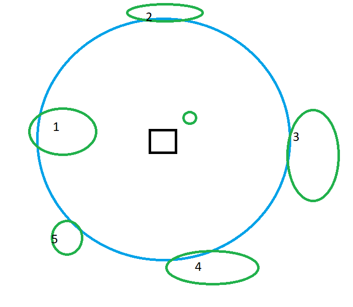
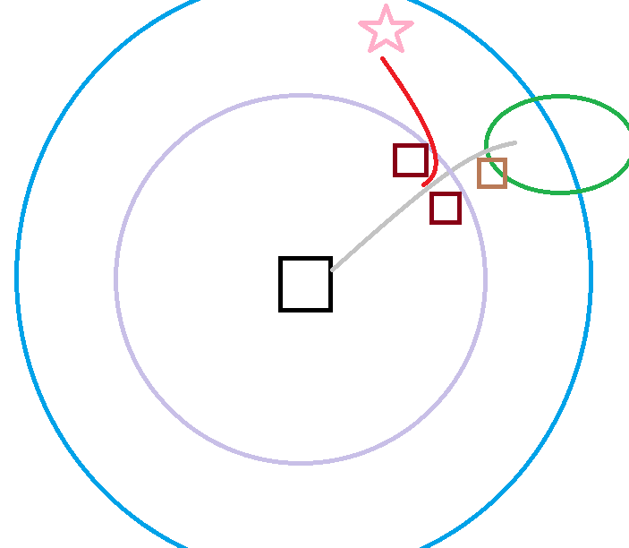
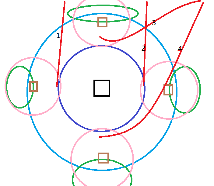
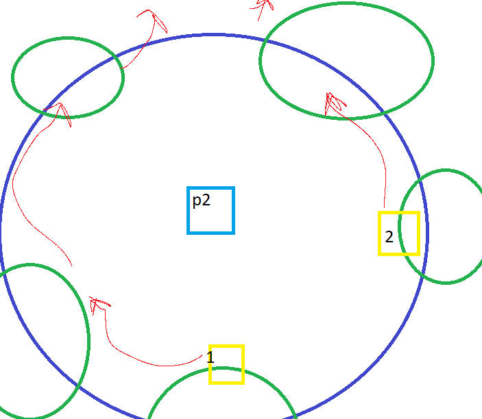
picking a proper starting woodline and properly positioning storehouses and other buildings is vital for optimal economy growth and security. proper woodline(s) management is vital for proper men and women positioning early,mid and late game. 1.everything about first 0-5 min. 2.middgame(after first few min) to till u reach p3. 3.endgame(after p3) 1.to start with your first woodline will significantly impact your economy and security. usually you will want to pick a patch of wood around the border instead of opting for placing your first storehouse near cc wood but exceptions apply.ill note thoes later. prioritize following factors listed from most important first: 1.how close the wood patch is to your cc 2.the size of the wood patch 3.the position of the wood patch 4.i forgot something while scrolling up to add hope i remember. 5.properly rotate and position the storehouse to be close to as many trees on the surface as possible. now of course you must pay attention to all 3 of these factors and alot of point 3 is better than a slight bit of point 1 but the significance based listing still applies. woodline.png shows several options. here based on 6 total options including the cc wood option 1 is the best as it is the closest to the cc and has a large amount of wood. its most important to pick a woodline that is as close to cc as possible.while these factors may not cause significant difference to less expirienced players its best to learn the most optimal ways from the begining.closer the woodline is to cc the less distance your units will have to walk to security if you get rushed and choose to retreat.many times if you pick the incorrect woodline you lose by default if you get cavrushed assuming both sides play without making any errors you just wont have the time to reach security. i recomend placing house(s) next to but not in the line the new spawned units have to walk form cc to the wood.if you were to place it on the line you would hurt your eco by hindering your units from quickly going to the woodline.also do place the houses within your cc arrow range so that if the enemy tries taking the houses your cc will damage their units.if this happens also consider trying to garrison the house under threat with women but only if enemy units are that of a low range type and only if your women can safely garrison.you place your houses like this so that you can do the garrisson>ungarrison trick with wood women if enemy rushes to decrease the distance you need to travel to cc and to increase the security.also the buildings will block the enemy from taking the shortest route to your women when he is rushing as you can see with the pink start representing enemy rush units and the red line representing the detour they have to take. for a barack you can use it as a blockade same as the upper house in that picture or you can place it above or around the woodline as barack can be a powerful defensive tool.it is quite difficult to take assuming you at least have a small part of the mencount of the enemy rush army.dont know the exact proportions but with barack garison>ungarison trick as a threat enemy will think twice before getting close to your baracks as you can quickly ungarison your units onto the enemy units gaining the advantage in certain scenarios. the size of the wood patch is self explanatory its value is that you can load it with more men and itll last longer before you have to switch lines compared to a smaller wood patch and by this it gives an economy advantage as you have to pay the toll of switching woodlines later than you would have otherwise. the positioning implies that you want to have the woodline as far away form the enemys potential line of travel as possible which basically means you want it at the back.the enemys line of travel is : assuming your enemy is competent:first he will know where your woodline is before atacking you.then he will engage inbetween your cc vision range(larger than attack range ccvision:blue) and your woodline mens vision range(pink) from either side of the 2 circles intercepting. this will allow the enemy to get as close as possible before you see him and to be as close to cutting off your wood units from security as possible. as the enemy will come from his cc the shortest route will be if you have your woodlines on the sides where he can intercept them by just taking a direct line and they are quite close as they are somewhat upfront. the front woodline is slightly better but pretty much the same as enemy has to go around it and to the side which wastes slightly more time as they have to walk around a circle that is slightly larger than your potential vision so they wont get spotted by the rule of thumb of not seeing any of the wood on that line>you cant see them.still these 2 options are near identical. the best one is the back wood as it takes the enemy far longer as the distance is longer and every second counts in 0ad especially in higher level games. last bit for the early positioning is the cc wood.if conditions are abysmal and you have no close woodlines(lets say overlaping the teritory by atleast the width of one 10 pop house) and your cc wood is large enough(atleast 5 trees (1k wood) or more) you might choose to place a storehouse at the start on the cc wood but this is horrible as your cc wood is your lifeline in case you get rushed of secure wood to cut and if you deplete it form the start and get rushed you will have nothing.just remember to keep scouting and stay vigilant if you use up ur cc wood as if you get rushed youll be in a bad position.otherwise as well cc wood storehouse hurts eco as youll ahve to get an another storehosue quite quickly in few min after the few trees near ur cc run out. 2.midgame woodlines. this is where youll most likely start to need second,third and maybe even fourth (if you are really unlucky) patches of wood utilized by your woodcutters. basically you shouldnt overcrowd a woodline as units will need to walk to a single storehouse and if overcrowded will be bumping into eachother ruining efficiency.optimal limit depends on specific civ storehosue size,woodline size and specific wood layout. a good rule of thumb is to literally never put more than 30 units on a single woodline or atleast depositing on a single storehouse. its best to start a new woodline after 20-25 units are on the first one.this may vary mainly depending on woodline size but also on storehouse size. when picking a second woodline make sure to place it with a path in mind. both woodliners must as game progresses emigrate to the front slowly but surely as you want your units as close to the enemy as possible during the late game for a variety of reasons.for example in this case: if your first woodline 1 is at the back you wanna imagine future migration paths forboth woodlines.had you placed your second storehosue closest to the first one the first line would have to walk longer to a nearest lone and this is especially bad if your first woodline isnt at the back and you block the front adjacent line forcing ur first line to move back upon exausting the wood patch.but i wont draw that i just wanna finish at this point. also make sure to have proper map awareness and secure the awareness of the p3 woodlines by patrolling and placing watch towers not to get denied proper woodline positionging late game (see the late game section for more) this is especially important against colony civs as they can very quickly build leaving you little time to prevent and this is one of the reasons you must have front placed men even during a large part of the middle game so they reach intime to defend you phase 3 reachable woodlines,place baracks at the front not the back at this stage. also dont be afraid ot get baskets if you have overcrowded woodlines and no better options. 600 res is often worth it to reduce the walktime.im gonna guess that you can place proportionally more units so if max was 30 and u boosted capacity by 50% u can place 45. 3.endgame at this point the relevance of mapcontroll skyrockets as you are going through woodlines like one of thoes advanced deforestation machines.you have alot of woodcutters and the 50% efficiency upgrade so you can easily run out of not only properly positioned wood(where placing men is good as if enemy atacks you an respond well where your men arent out of line of defending your key points cc,baracks,caslte ect/) anyway at this point you wanan make sure that you will have proper woodlines by also patroll and outposts so enemy wont palce a civic building or tower your woodlines.you can ofcourse do these thigns to hurt your opponent as well.here its a good idea to have some units preferably largely women for total eco viability as back then it wouldve cost far less to get women and now you can send most of your men to atack instead of having men cut wood while other men fight or having to move women from farms.anyway its a good idea to have a group of units cutting wood from the back,out of position as this boosts your total wood avalibility by you spending less of the well positioned wood and as this little group consisting partly of women being out of position wont hurt your security in any significant manner. if you see that in the future you wont have optimal woodlines either reach for some by palcing buildings on the edge and building to the woodline over time or place a civic building if you think thats the right move.most importantly you must decide and notice in advance as if you run out when the time comes withotu any prep you will be in a bad position disadvantaged by having either no woodline or a bad one at the back.and when enemey atacks your units wont make it in time and youll lose :p. hope this helps heres my donation adresses bitcoin- bc1qhp8xa956p2veyd0mmf328tp2rmmuuvez5cnxlz monero - 84iSSAx1H6mWG7z49sgcBe7ZWfLHoQp4TCMcpnq94KZpGPKqRehMZ8LeKMpADRaiCEMSJKmcueLU1HLtPTqu6nDQRQDNU9o
-
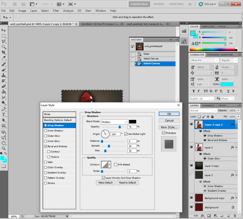
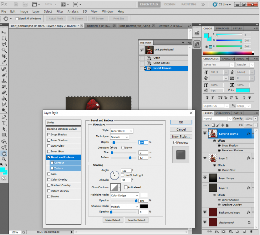
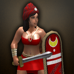
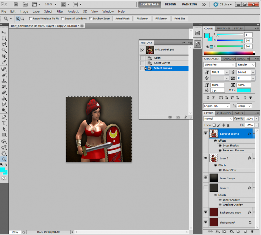
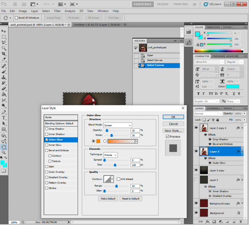
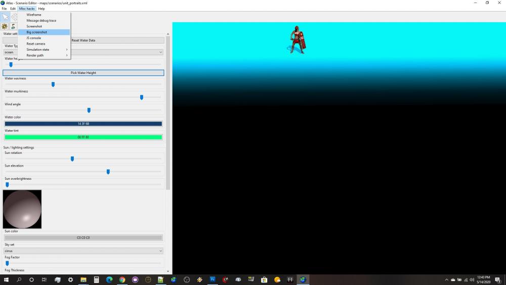
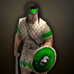
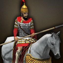
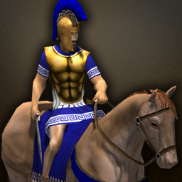
1. Here is the standard background I use: 2. Taking a screenshot of the unit in Atlas with the "Big Screenshot" option, it looks like this (note, I use a custom scenario map with a bright ground texture for ease of cutting in Photoshop) 3. A. I cut the unit out of the background, B. copy the unit into a 2nd layer (this is important), C. resize it to 256x256, D. then add the background texture at the top of this tutorial. E. From there I adjust the Layer Styles (effects) of each of the unit layers to give the final product. This is what the file looks like for me: 4. These are the layer settings I use. First, to get that nice brownish background glow (THIS IS WHAT IS MISSING FROM MANY OF THE NEWER PORTRAITS IN THE GAME): 5. Here, I create the drop shadow effect: 6. Sometimes I add a subtle Bevel and Emboss to help the unit stand out a bit from the background. THIS IS SUBTLE, and usually used on a unit with dark edges, like dark hair or a dark horse. Sometimes I don't even use it. As an example, I used this effect to make the Balearic Slinger's head stand out a bit more, otherwise it would have blended into the drop shadow. 5. Here is the final product: Further Examples: unit_portrait.psd
-
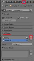
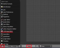
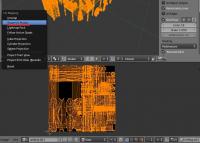
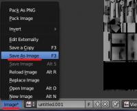
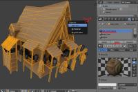
Introduction This is a guide covering how to import assets from the game to blender, create a second UV coordinates, bake the AO maps and export again. The game's buildings are usually divided in different .dae files (one per diffuse texture used) Usually, they consist in one main ".dae" file located in "meshes/structural" and one or more ".dae" children (props) that are attached to the main file, this "prop" daes are located in "meshes/props". (this is not always the case) In this example, we're going to bake the AO map for the celtic civil centre. 1.- Import the mesh into blender3D Inside blender, remove the starting cube, camera and point light. Go to file->import-> Collada (.dae) and select the .dae file to import. This building consists on three files: celt_civic3.dae, celt_civic3_props_1.dae and celt_civic3_props_new.dae If blender shows an error importing: *Note: The file may be imported rotated -90º in the X axis. To solve this, simply center the pivot point at the origin with SHIFT+C, select the cursor for your pivot point, select the asset and hit "R" for rotate, "X" for the axis, and then type "90" on the numpad and hit enter. Each time you import an asset, it is important that you create a new material with the name of the .dae or the texture that is going to use if you know it. This will let us separate the object again after we join all the meshes together. 2.- Set up a new UV coordinates. Select all your meshes and join them with CTRL+J Go to "object data" panel, scroll down to UV Maps menu and click the "+" sign to create a new UV coordinates. --Select the building, enter in edit mode with TAB. --Open a window with the UV/Image editor. Click in "new image" and "ok" in the pop-up menu. This creates a new 1024*1024 black image where we will bake the Ambient occlusion. --Now let's unwrap the model automatically. Go to object mode, select the model, use "CTRL+A" and select "apply scale" this will recalculate the scale of our building, so the polygons could be unwrapped nicely. --Enter "edit mode" with TAB. select all with "A" and hit "U" and select "Smart UV Project" in the pop-up menu. --In the next menu select the following settings: 3.- Baking the AO into our new generated black image. Preparing the AO settings: go to the "world" tab in the settings panel, mark the checkbox of Ambient occlusion and set it to "multiply". Scroll down to the "Gather" pannel and change the samples to something between 20-25 --We have the model ready to bake the AO map. Go to the render tab, scroll down to the "bake" panel (click on the "bake" pannel if it is closed) and use the following settings: --Then click "bake" and wait until the baking process is completed (this will take a while depending on your machine) --Once finished, you can hit "N" in the viewport to open a toolbar, go to the "display" menu, and click in the "texture solid" checkbox. This way you can see the AO map we have just generated on the model and check if it has been correctly generated. ------If you see black strange black faces where it shouldn't, the polygon normals are probably facing the wrong direction. This could be fixed selecting the black faces and then hit "W" and select in the pop-up menu "flip normals". ------If you find the problem where there are dotted black parts, it's probably because there are two or more polygons overlapping each other. You'll have to tweak the model sightly to fix this issue. --Once the bake is finished and you're happy with it, remember to save the image generated so it doesn't get lost. In the UV editor select Image->save image As... 4.- Separating the mesh by materials Now that we have our AO map, and the model has a second UV coordinates for the AO, we have to separate it's pieces again and export the parts one by one. To separate by materials, enter "edit mode". Make sure you don't have anything selected hitting "A" twice. Go to the materials tab, select the first material on the list, and click "select" button. This will select all the faces that have that material assigned. Once selected hit "P" and select "selection" in the pop-up menu. Repeat this step for each material (prop) you have imported. NOTE: Now that you only need to export the objects into .daes again, is a VERY NICE moment to save the .blend file in case the export process goes wrong. 5.- Exporting the meshes back to .dae files. This is the last part. You have to export the objects one by one. Make sure the following requirements are met: - There's nothing else on the scene except the mesh you want to export (even hid objects breaks the export) - You have to remove every material applied on the mesh. - There are no lights, armatures or other objects in the scene. - You have your object selected. Then you simply go to File->export-> Collada (.dae) and select the file to export or overwrite the old one. After that, reload the .blend file and repeat this step with the rest of the objects (or hit CTRL+Z a few times until you get back the other meshes and repeat the process with the next one) I hope it's somewhat understandable and useful .
-
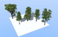
Hello! I'm back with a quick tutorial on how to make lowpoly trees taking advantage of Blender's 3D add-on "sapling tree generator" in less than 10 minutes! Here's a video tutorial from BlenderGuru with more in-depth information about how sapling add-on works: http://www.blenderguru.com/tutorials/how-to-make-a-christmas-tree/#
- 28 replies
-
- 10
-

-
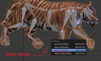
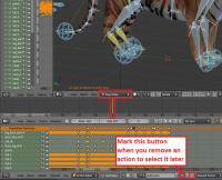
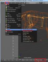
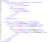
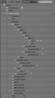
An updated version of this guide is available on the Wiki. Introduction This is a guide covering how to export and set up animation files from Blender3D into 0AD as well as some tips and general guidelines for get the animations working in 0AD. The Blender3D version used for this guide is 2.65a newer versions might have problems with the Collada exporter. Last blender version (2.69) works fine for exporting animations. Animations have three main requeriments in order to get them working in 0AD. These are: 1.- The file with the mesh and armature (COLLADA file) 2.- The file(s) with the different animations of the armature (COLLADA file(s)) 3.- The file XML defining the armature (called skeleton in 0AD) with its bones names and hierarchy. The last step is to specify the animations that the unit will have available on its different states in the XML actor file of the unit (i.e. Walk, run, death, idle...) Rig setup: When setting up the rig to animate your mesh, there are a lot of options to configure it to make the animator's life easier and achieve good results with less effort. Sadly, there are some limitations in how much animation and skeleton data the COLLADA format can export. Here are some points to keep in mind when configuring your rig to make animations for 0AD: -Avoid disabling "inherit rotation" in bones. While it's a very nice blender feature, when exporting your animation the bones that have their inherit rotation checkbox disabled end up inheriting their parent's rotation, plus the extra rotation you add in the animation resulting in weird and undesired behaviours. There's a tricky workaround for this, which is creating a helper bone which the bone that you don't want to rotate will copy its rotation. -Make sure the rig have the correct scale, and has its scale applied before start animating. Resizing your rig and/or mesh and applying its new scale before baking the animation may end up messing the animations you may already have, specially if you have any IK (Inverse Kinematics) setup in your rig. Here's a workaround that may or may not work: -Scale to the correct size the mesh+armature file and re-export it. -Export the baked animation(s) to dae with their incorrect size, but correct animation. -Import them back into blender, scale them correctly, and export them back without applying the scale one by one. -Mark the "Clear Constraints" checkbox when baking an action if you use any IK or constraint. Specially if you use constraints like "copy rotation" and "copy location". Once the action is baked without "Clear Constraints", it may appear in blender that it worked fine, but it will not when exported to collada format. -Save your .blend file before exporting. You will lose your rig constraints when baking the animation, plus importing collada animation files back to blender is not working propperly to date (11/24/2013). Because of this, if you want to tweak an animation, or use the same skeleton/rig to create a new one, the only way to do it right now is using the .blend file. In this guilde, we're going to set up the animations for a wild animal unit "Tiger" that will be controlled by the IA "Gaia". 1.- Export the .DAE file with the armature In this step, we're going to use Blender3D to create the first main file needed for the unit's animation. This file tells the engine the relationship between the bones and the mesh. Before this step, you should create in Blender3D the armature (skeleton from now on), and the mesh that is going to use it, apply the skeleton to the mesh and tweak the vertex wheights that each bone will move (this is not covered in this tutorial). Before exporting the mesh and the armature, you should make sure that both objects are centered in the origin point of the scene and both object's origin points locations match. To move the object's origin points to the scene origin point (coordinates 0,0,0) first use "SHIFT+C" this will make your 3D cursor to center into the scene origin, then select the mesh and the skeleton with rightclick and shift rightclick and use "CTRL+ALT+SHIFT+C", in the pop-up menu select "Origin to 3D cursor". Now make sure you remove from the "action editor" any action currently used by the skeleton (if any) and move the timeline back to the first frame if it isn't there. [1b – Optional image removing the action editor's action] Also make sure your skeleton is in the default pose (also called resting pose). To do this, select the skeleton, use "CTRL+TAB" to enter pose mode, hit "A" to select all bones and use "ALT+G", "ALT+R" and "ALT+S" to reset the bone's position, rotation and scale, this will put the armature in it's resting pose. Now we're ready to export the mesh and skeleton. Make sure there's nothing else in the blender scene other than the armature and mesh (remove lights, other meshes, helpers/empties...). In "Object Mode" select the mesh first with rightclick and then the armature with "shift+rightclick" (the order is important) then go to the menu in the top of the screen and use "File --> export -- > Collada (Default) (.dae)" Navigate to the folder where you want the file to be created, name the file and hit enter or click Export. *Note: These "mesh+armature" files are stored in \0AD\binaries\data\mods\public\art\meshes\skeletal\ 2.- Export the .DAE file animations In Blender3D, you have to use the "action editor" to create the different actions (or animations) that you want to export into 0AD to use them. These actions are usually: walk, run, idle, attack, and death, but you can make variations of each one or make more types of actions if desired. This tutorial do not cover how to animate in Blender3D but I'll give you links to animation tutorials and tips for the animations at the end of it. 2.1- Bake the action to keyframes In 3D animation software, you animate inserting keyframes or "posing" your skeleton along a timeline, and then the software computes the space between keyframes with intermediate poses which makes the movement motion. The closer one keyframed pose is to another, the quicker the motion will be from one pose to another, and the further the keyframed pose is to another, the slower the motion will be. To make an animation file readable for 0AD, you have to bake the action into keyframes in Blender. This is the process of creating a keyframe for each frame if a bone has changed its position from the previous frame. This is done automatically by Blender3D when baking the action. To bake an action into keyframes, first select the action to bake in the action editor, then adjust the "start frame" and "end frame" on the timeline to match the action length. After that, select the skeleton, enter in pose mode with "CTRL+TAB" and select all bones with "A". Once you have selected all bones, move the mouse cursor into the 3D viewport, hit "space" to bring the search option menu and type "bake action" then select "Bake Action" in the menu. A menu for the "Bake Action" option will emerge, uncheck "Only Selected" checkbox, !and check "Clear Constraints" checkbox (specially if you use IK and/or constraints) and click OK This will automatically insert keyframes between the poses you used to animate. 2.2- Export the animation .DAE file This is the same process as the first point. This will create the file containing the actual animation that will be played in 0AD's engine. Switch from pose mode to edit mode with "CTRL+TAB" select the mesh first with rightclick, then the armature with shift+rightclick, go to "File --> export -- > Collada (Default) (.dae)" Navigate to the folder where you want the file to be created, name the file and hit enter or click Export. *Note: These animation files are stored in \0AD\binaries\data\mods\public\art\animation\"unit type"\ **Note2!!: Units with different meshes but same skeletons can share these animation files and use it even if the animation files have been exported with different meshes. However, each unit needs to have its own "mesh+skeleton" .dae file that we have created in the first step. Repeat 2.1 and 2.2 for each animation of the unit and name them accordingly (i.e. tiger_walk, tiger_death, tiger_idle_01, etc...) 3.- Create the XML file defining the skeleton 0AD needs a .XML file to define the skeleton's name, bone hierarchy and bones' names. These skeleton .XML files are located in "\0AD\binaries\data\mods\public\art\skeletons\" You'll need one skeleton .XML file for each different skeleton you want to use in 0AD. The easiest way to set up one, is to open an existing file and modify it with the information of the new skeleton you want to add and save it as a new file. You can open .XML files with any text editor software. I recommend notepad++ to do so (personal preference). This is an example of the syntax that you need to use to setup the file correctly: Note how each child bone is defined under its parent bone line before closing the parent's bone definition with "</bone>" The RootBone is the bone in the armature that controls every other bone in it. Note: If you have any bone name in the skeleton containing a dot "." you have to use an underscore "_" in this file instead when writing the bone's name. To know the hierarchy of your skeleton, you can use the outliner window in Blender3D and expand the armature contents. There you can see which is your root bone, and the childs of each one of them. Once you have completed setting up the file, use "save as" and save the .xml file with an appropiate name in the folder specified at the beginning of this section. -Specifiying the animations for the unit in its actor Every unit (or entity) in 0AD has it's own .XML file which contains information that tells the engine different properties of that entity. These files are called actors. Some properties that contains these actor files are: -Mesh: the mesh that will be displayed in the engine for that entity or unit. -Prop(s): Actors can be used within other actors. They're called props. You need an empty/helper/bone with its name starting with "prop-" to specify where you want the actor to be shown. -Variants : These are possible variants of a unit (used for unit diversity) as well as states that a unit may have. -Texture(s): The texture or textures that the mesh will use. -Animation(s): Animations that the unit or entity can use and the variant/state associated with that animation. Animations in the actor files are normally specified just before the <mesh> tag in the following format: The <animation> tags in this example include the location and filename of the animation (created in section 2), the name of the variant/state that will use that animation specified by "name=", and the speed that the animation will play. The animation speed gives you control over the speed that the animation will play independiently of the speed it had when exported from Blender3D. Loading and hiding props during an animation: There's a special case for animations where you can load prop's actors and make them dissapear during the animation. The first animation specified in the example with the variant name "Build" uses this case. You specify with fractional numbers when the prop will show up with "load=" and when it will dissapear with "event=" during the animation. The number "0" means the start of the animation and "1" the end of it. The variants are normally specified after the textures in the actors. Here's the variant definition of "Build" from the previous example: In this example the actor "wood_1_a.xml" is going to be loaded at 25% of the duration of the build animation, and it will dissapear at 75%. You specify where the prop actor will be placed with "attachpoint=" . The attachpoint value needs to be the name of a bone, but it is mandatory that the bone name starts with "prop-". When you specify the prop-bone name you ommit the "prop-" part of the name, but if it's declared in a variant that is going to use "load=" and "event=" you have to start the name of the prop-bone with "loaded-" (in this example, the bone's where the actor is going to appear is "prop-beam". Note*: For static meshes without skeleton, you can use empties parented to the mesh with the name prefix of "prop-". You can later use this empty location to spawn an actor on it's place when defining the props between the <prop> tags right after the <mesh> definition in the actor file. 2015 Edit: - Blender collada export now works better and there's no need to bake the animations even if using IK setups. This reduces considerably the size of the animation collada file. - In order to get clean loops in pyrogenesis, you have to export including the first and last keyframe of the loop. In theory, it is the same keyframe and should be avoided, but the engine needs this duplicated keyframe. In resume: export the first and last keyframe in the animation loop to get a clean looping animation. - Blender now supports "clean channels" option when selecting keyframe channels and deletes the keyframes that do not add anything new to the animation. This reduces the size of the animation file without altering the animation at all. Just select all keyframes in the action editor, hit "X" and select "clean channels" Rigging Tutorials: http://vimeo.com/30073532 http://vimeo.com/30072564 http://vimeo.com/30078317 Animation Tutorials: http://www.cgmasters.net/free-tutorials/epic-looping-idles/ http://cgcookie.com/blender/2011/08/22/animating-a-character-picking-up-an-object/ Import/export 0AD assets and AO baking: http://www.wildfiregames.com/forum/index.php?showtopic=17542&p=273078
-
Hello everyone, I didn't see any totorial to explain how to change the GUI. So, I will try to write one. I'm not English, so if they are mistakes, moderators could edit this. I will update this tutorial when I will found new things (I learn from analysing the source code). Customize your Gui 0.Create a mod 1. Add a new panel 2. Coming soon ... 0.Create a mod Go in the folder where you install 0ad : "0 A.D. alpha" then into "0 A.D. alpha\binaries\data\mods" Create a new folder with the name of you mod (replace space by _) Go in "0 A.D. alpha\binaries\data\mods\public" ; copy "mod.json" in your own mod directory Edit the file with Notepad++ : after "label :" delete "0 A.D. Empires Ascendant" and enter the name of your own mod ; you can also change the description Congratulations ! Now your mod appears in the mod selection of 0ad ! 1. Add a new panel In the directory of your mod, create these folders : "\gui\session" Go into the public mod folder (0 A.D. alpha\binaries\data\mods\public) open the zip file and then go in gui\session. Copy session.xml and sprites.xml in your own session folder. Edit session.xml with Notepad++ : line 103 add "<include file="gui/session/the_name_of_your_panel.xml"/>" Edit sprites.xml : after "<!-- Panel Backgrounds -->" (line 27) add : <sprite name="the_name_of_your_sprite"> <image texture="session/folder_of_my_pictures/name_of_my_background_picture.png" texture_size="0 0 100% 100%" size="0 0 100% 100%" /> </sprite> 5. Create in the folder session a file named the_name_of_your_panel.xml , then edit it : <?xml version="1.0" encoding="utf-8"?> <object name="the_name_of_your_panel" type="image" sprite="the_name_of_your_sprite" size="coordinateX1 coordinateY1 coordinateX2 coordinateY2" tooltip_style="sessionToolTip"> </object> You must define the placement of your panel with its coordinates. 6. Place the background picture of your panel in name_of_your_mod\art\textures\ui\session\folder_of_my_picture\name_of_my_background_picture.png Launch 0ad and activate your mod. Your panel is now present during your game !
-
Hello I thought it could be interesting for 3D artists and future 0AD contributors to get advices, tips, good links, interesting tutorials, etc. So why not sharing them here?
-
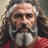
how create face texture for the units,in order give more variance, and learn to apply the whole project (including mod) for example this face...
-
Hi all, Newbie here. I just played 0.19 64-bit. It took me quite some time to figure out where the tutorials are. http://trac.wildfiregames.com/ticket/2303 is obviously needed and hopefully it will come in alpha 20. What I don't know is what to play after that. There doesn't seem to be any scenarios which build on the first one. Also is there an option to see the tutorial messages for a longer time or to see what announcements or messages I missed in the game ? That actually should be part of the tutorial itself so newbies like me where to look. Also in the introductory tutorial, there are three resources, food which is either berries or farming, wood and stone. Metal is nowhere to be found nor is any explanation of a fifth resource which has an icon but no name, some sort of reputation or something (don't really know) and there is no way to know how that is added/earned. Even how territories are expanded are not known.
-
I found this in a weblog about this, is some commercial stuff but basic to improve drawing special color, shadow and some advanced. If you know use gimp you can try it. It's not Photoshop exclusive Source: http://cgcookie.com/concept/cgc-courses/citizen-christmas-present/ Even they are in Deviant art.
-
i have two questions: * how capture gaia horses and elephants, the elephants fight, and horse flee, but catch is impossible i only "eat" it * how Run???? with mouse button i get walk the units but Run, i don't know

.thumb.png.ce58cea22940c255f5b0a735d5abee36.png)

