Search the Community
Showing results for tags '3d'.
Found 15 results
-
 Here are some tutorials for making procedural materials (Materials that doesn't exactly need a texture image for looks good) Have fun. Eyes making https://en.wikibooks.org/wiki/Blender_3D:_Noob_to_Pro/Advanced_Tutorials/Procedural_Eyeball_in_Cycles Marble/Stone like materials and Cracks/veins https://cgmasters.net/free-tutorials/blender-cycles-tutorial-stonemarble-how-to-make-any-texture/ Letters animations (Maybe for making introduction videos).
 -
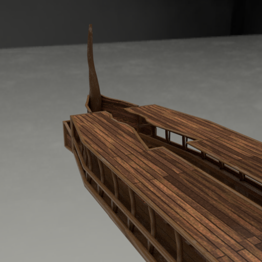
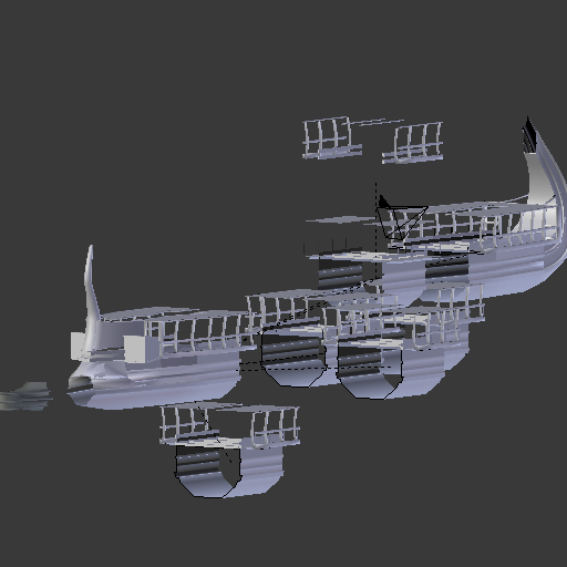
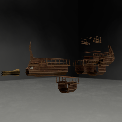
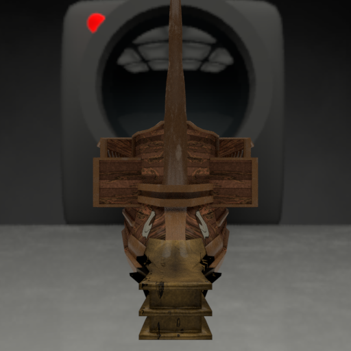
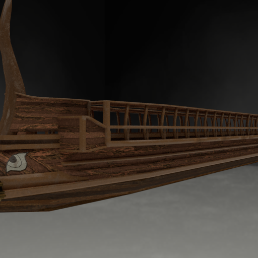
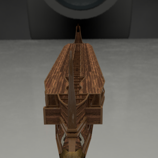
Hi!, i have been working on a high poly model of an athenian trireme based on "Olympias Trireme" for later bake on a low poly one and for fun. Here are some screenshots: Its also Modular for easy modyfing: Gonna be adding details and everything i can see on the references i have, and finaly leave the 3D model as a 3D Tour on Sketchfab in name of 0 A.D.
- 203 replies
-
- 12
-

-

-
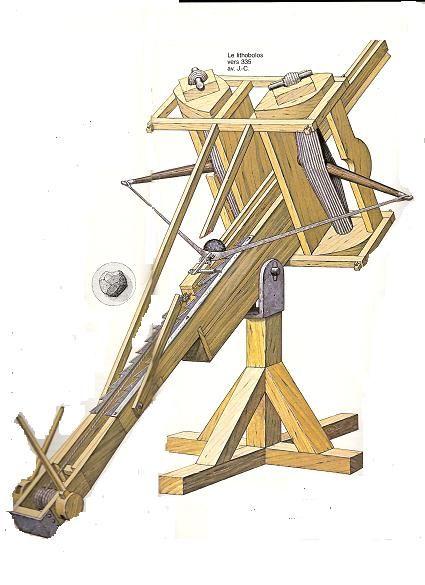
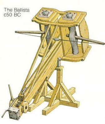
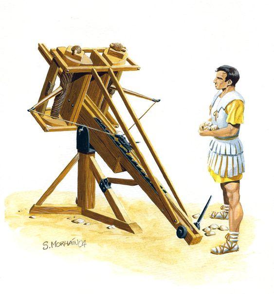
Upcoming new artillery preview: Small 2 Operator lithobololos: For those who always asked for a "Tower" Artillery, this could fit a tower (and if it doesn't tower will fit on it). Following references made this siege artillery wich is an smaller version found on a reference but not seen only one but multiple times, specially on some artistic drawings of macedonians on a river using it wich can be appreciated that isn't that big in some cases and it does in others. So the point is Split artillery in 3 Classes. Light Artillery: Oxybeles/Polybolos/Scorpion. Fast shooting light artillery, good agaisn't infantry. 1 - 2 operators. (Yes the plan for modders (not main game) could be upgrade wall towers into roofles towers for small artillery). Med Artillery: Lithobolos, Roman Ballista Medium size ideally for ambushes were the artillery is faster to move carried in a wagon as usual but with shorter range and smaller stone projectiles. 2 - 3 Operators Heavy Artillery: Roman Heavy ballista, Carthage Heavy Lithobolos, Reinforced Heavy lithobolos. Ideally for besiege towns from a long range, Expensive specially on wood, acquirable only by some factions, stronger, slower than a Ram and if its possible it should be good to have a Tech to unlock them,. 4 - 6 operators This could make artillery a 3 phase gameplay being workshop available at 2nd phase unlocking only light artillery, Med artillery and Ram at 3rd Phase and Research about some kind of education recquired by the greeks and romans of that era wich allowed them to do this possible). This is only my thought, this isn't a gameplay choice im placing above all other decisions. But thats my plan, Hopefully maybe someone add it to a mod or maybe it reaches main game. Some references i have for my plan:
-
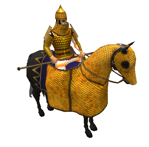
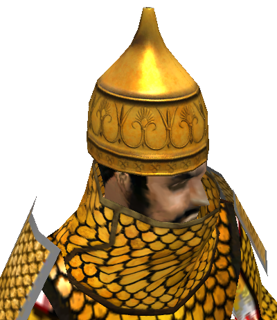
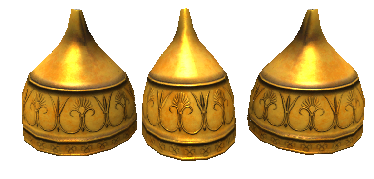
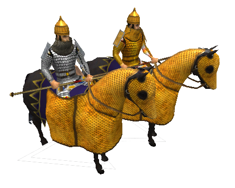
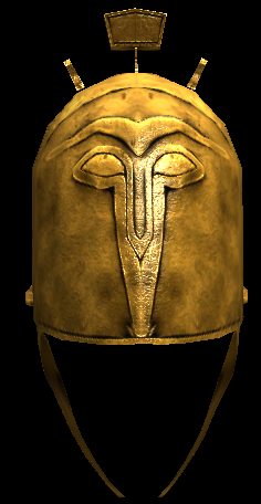
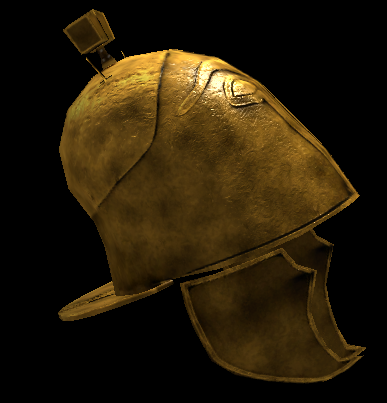
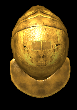
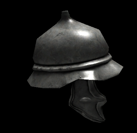
Hello 0.A.D. Community is time to give some love to persians due the recent changes to other civ assets, even when they have the most detailed cavalry assets, their infantry assets like helmets and shields are pretty much outdated. Its time for some persian love... Starting with the recent changes to chamfrons: And this new helmet (Missing Plume): Texture of the helmet is 1024 for have a cleaner bake due the amount of detail: Plus the new neckguard, Thought the iron bake went a lil bit darker than supposed to be. If any1 find references for the conical helmets, feel free to post'em here it would help me to properly find their conical helmets.

-
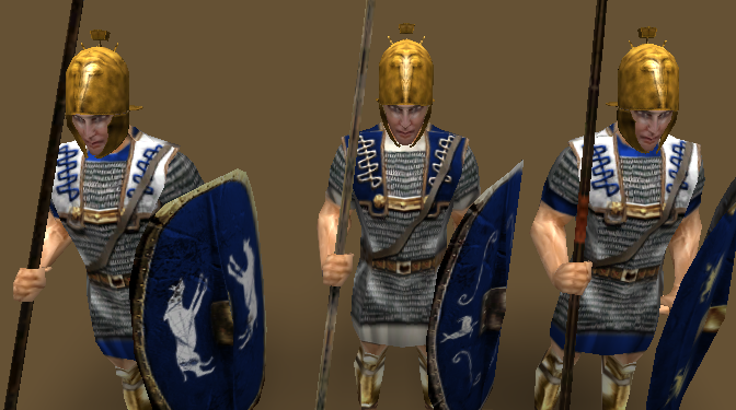
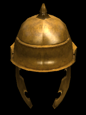
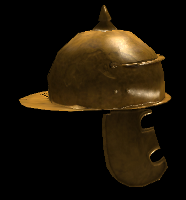
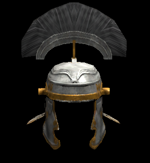
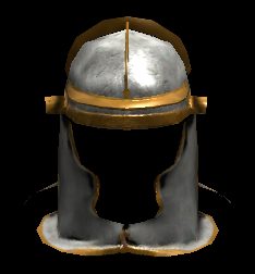
Another topic for helmets, for now i have this: From other topics i have this: The first helmet its recorded but says its damaged because my secondary hard drive is damaged so i used VLC to fix the video now its only visible through that program, i'll see if YouTube could handle the video later.rome_helmets.7z

-
 Indeed. that's why you need use something similar to my suggestion. The Capitoline She-wolf (Italian: Lupa capitolina) takes its name from its location—the statue is housed in the Capitoline Museums in Rome. The She-wolf statue is a fully worked bronze composition that is intended for 360 degree viewing. In other words the viewer can get an equally good view from all directions: there is no "correct" point of view. The She-wolf is depicted standing in a stationary pose. The body is out of proportion, because its neck is much too long for its face and flanks. The incised details of the neck show thick, s-curled fur which ends with unnatural beads around the face and behind the forelegs. The wolf’s body is leaner in front than in the rear: its ribs are visible, as are the muscles of its forelegs, while in the back the musculature is less detailed, suggesting less tone. Its head curves in towards its tail; the ears curve back. The children themselves have a more dynamic posture: one sits with his feet splaying to either side, while the other kneels beside him. Both face upwards. They, too, are lean, with no trace of baby fat. https://www.khanacademy.org/humanities/ancient-art-civilizations/roman/roman-republic/a/capitoline-she-wolf
 -
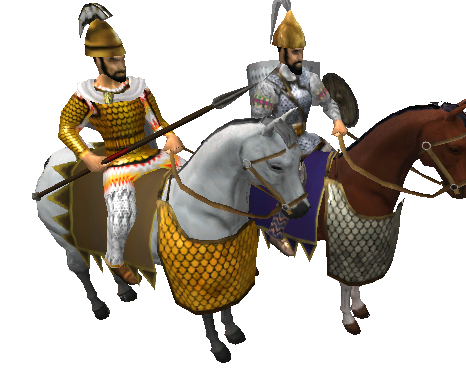
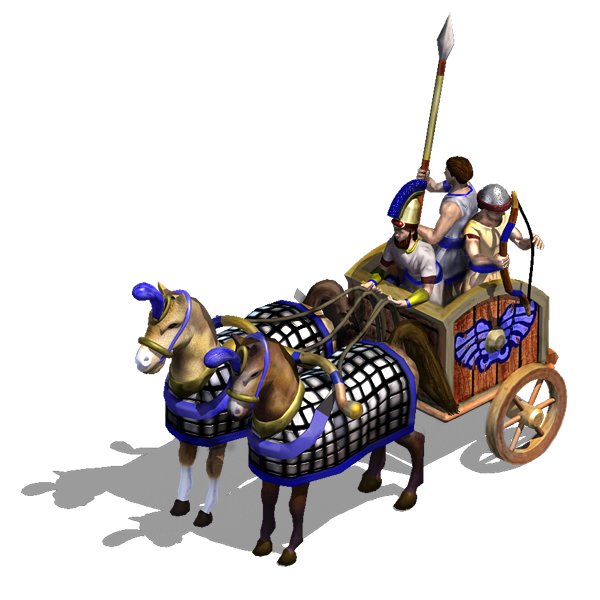
Needs to be for 2 passengers, anchor for 4 horses. Just the chariot no horses. Bonus: textures for the two units in the first image: Hey! here is some help in how to create textures in Blender!
-
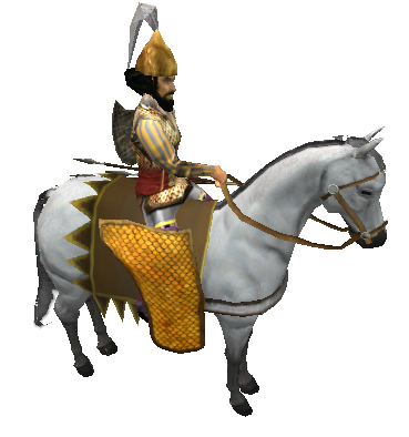
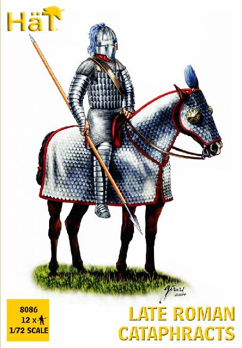
Full body armor Persians and parthiansc and their pants. Indie pants
-
Introduction. Ok, open topic in order have plenty of sources and visual reference that's preceding to art task. We started with Classical Greek and Persian around 650-450 BC. https://en.wikipedia.org/wiki/Ancient_Greek_military_personal_equipment
-
.thumb.png.ce58cea22940c255f5b0a735d5abee36.png) Share Simulating Real-world Film Lighting Techniques in 3D Updated September 9, 2011 By Lucy Burton Source: https://software.intel.com/en-us/articles/simulating-real-world-film-lighting-techniques-in-3d With all the advances in modeling and animation, an often overlooked but absolutely critical area of 3D scene creation is the proper use of lighting and rendering techniques. Good lighting and rendering can make even a simple 3D model look extraordinary, and poor lighting can make even the best model look bland. This series of tutorials cover not just the mechanics of lighting within the Autodesk* Softimage*|XSI* software package but also how to incorporate the language of light used in fine art, theater, and film into your 3D scenes to create truly cinematic views that are compelling for your audience. I'll explore the basics of real-world lighting scenarios and how to implement them in 3D, and because rendering is inseparable from lighting, I'll also discuss various rendering techniques such as Global Illumination, Final Gather (FG), Ambient Occlusion, and of course, high dynamic range imagery (HDRI) lighting. Light and Shadow In music, the silence between notes is as important as the notes themselves for creating emotion within a composition. Similarly, in lighting, shadows-their placement, direction, intensity, softness, and so on-are just as important as light in creating meaning and mood within a scene, as Figure 1 shows. Figure 1.This still life demonstrates the importance of not just light but shading to a scene. Notice that although the image on the left is well lit with Global Illumination and FG rendering, it is still relatively flat. But with the addition of the directional shadows in the right image, cast courtesy of the Physical Sky shader in Autodesk* Softimage*|XSI*, light passes through a window, a curtain, and shadows from the leaves outside, and the scene gains additional visual interest and realism. More often than not, beginners take one of two approaches: either flooding the scene with flat light as if merely seeing the objects is enough for the viewer (or worse, simply bumping up the ambience to fill in poorly lit areas) or not lighting it enough in order to hide shortcomings in modeling. When used properly, however, both light and shadow can actually enhance a model or animated character, providing an additional layer of drama or suspense to the scene. Obtaining an understanding of these basics is critical to realizing your vision. Three-point Lighting Three-point lighting is derived from a technique originally developed for theater by Stanley McCandless, who is widely considered the premiere developer of lighting design in the United States. The variation used in film, television, and commercial product promotion uses three lights: a key light, a fill light, and a back light, each with a specific purpose. The key light (Figure 2a) is the main directional light on the object or character and is typically the brightest light source in the scene. The fill light (Figure 2b) is used to simulate the light bounced from objects and sources on the opposite side of the frame from the key light. Finally, the back light (Figure 2c) is used mainly to separate the character or object from the background by providing a slight halo effect off the back edges of the character, such as a hint of light at the rim of their shoulder or off the edge of its hair. Back light is not the same as background lighting, however. Three-point lighting is about illuminating the main subject, whether that's a character or the model of a product a company hopes to sell. Therefore, back lighting points toward that subject, not the objects behind that subject. Figure 2.These images show a standard three-point lighting set-up. Note how the rays are cast to light the figure and to differentiate the subject from its background; (a) key light; (b) fill light, and (c) back light. Autodesk* Softimage*|XSI* provides another handy tool for positioning your lights. By clicking the drop-down arrow of any 3D viewport, you can select Spot Lights, then choose any of the listed spot lights within your scene. The view will change to the perspective of the light itself (Figure 3) as if you were looking through it, directly at the object it is lighting. From here, you can see precisely how much of the object is receiving light and where the umbra begins. You can also interactively adjust the spotlight by pressing the B hotkey to display the light's manipulators, and then pressing the Tab key to reveal the manipulators for the cone and spread angle of the light. The white exterior cone controls the Cone Angle value; the inner yellow cone determines the Cone Spread value. Simply click and drag the cone you with to adjust, or Shift-click and drag the edge of the cone to manipulate both cones simultaneously. Figure 3.Autodesk* Softimage*|XSI*'s Spot view Key-to-Fill Ratios The main thing that key-to-fill ratios (Figure 4) determine within a scene is how "contrasty" your final image will be. Low key-to-fill ratios are excellent for creating desaturated looks, such as those of a cloudy day where the sky is overcast and muting any harsh directional light from the sun, or in places where there is a lot of bounce light from the surrounding environment, such as a hospital room or the white tile of a kitchen. Low key-to-fill ratios are also used for any atmosphere in which you want to create the impression of happiness, such as in a child's room. In this sort of lighting scheme, there is a great deal of fill light, nearly matching that of the key light. Figure 4.This series of images demonstrates a range of lighting possibilities. The first image (a) presents a standard lighting scheme; (b) shows a low key-to-fill ratio, and (c) a more dramatic high key-to-fill-ratio. The last image (d) demonstrates how a change of angle can alter the emotional character of the subject, making him look quite ominous, and even change the structure of the face. Examples of high key-to-fill ratios include scenes with deep shadows and bright highlights, such as the stark lighting of film noir classics like Touch of Evil, scary films like Les Diaboliques, or in the paintings of Rembrandt. In this kind of lighting, the key light is often set at a very high angle, producing sharp shadows and a triangle of light below the eye of a character on the opposite side of the face from the key light position. It is highly directional, and there is virtually no fill light on that side. Color Temperature Color can modify form and is a powerful visual and emotional stimulus within a design that can cause objects or characters to appear to change dimension, reverse directions, and alter the interval between forms. It can even seem to generate motion within a scene independent of object animation. The colors you choose within your lighting establish overall mood and reinforce the theme of the overall work. Color temperature (measured in degrees Kelvin [K]) varies depending on the light source in question. All objects emit light when sufficiently heated. The degree of brightness is a function of temperature. Through a device called a spectrophotometer, any color can be equated with the amount of temperature being applied to a blackbody, which results in a Kelvin measurement (Figure 5). Candlelight is very warm in color and varies between 1850° and 1950° K, whereas a typical household incandescent light is about 3000° K, producing a color ranging between orange and yellow. Fluorescent lights give off cooler color tones ranging from green to blue and are between 3200° K and 7000° K. Daylight ranges between 5500° and 7500° K. Figure 5.Color temperature chart in degrees Kelvin Your color choices in lighting are also important when trying to composite 3D objects or characters with live-action backgrounds. In addition, films are registered to certain color temperatures: Daylight-balanced film is 5500° K, and tungsten-balanced film is 3200° K. Even today's digital cameras use filters to achieve the same sort of effects, and on-set lights use specific gels to tint light sources. So, if you're working with photographers or cinematographers, you're going to need to get the shooting data from them if you're going to mesh your scene well with their work. Additionally, postproduction color timing used by film processors can change the scenic color balance. Adjusting Gamma Correction and Contrast Gamma measures the degree of brightness and contrast within the midrange luminance values of an image (Figure 6), either in a photograph or via a video or computer device. When video is encoded and decoded, variations in the contrast values of the image occur. In a typical cathode ray television, the gamma value is 2.2 darker than the original 1.0 gamma value of the video compression that a camera records. Additionally, there are differences between Windows and Mac systems, with Windows gamma encoding being 0.45 and the gamma decoding being 2.2. Mac OS X and later versions encode gamma values at 0.55 and decode gamma at 1.8. A Nintendo Game Boy displays images with a gamma value ranging between 3.0 and 4.0. Figure 6.This series of images of a blue frog demonstrates how gamma affects an image. The second image from the left should be ideal for most devices. What all this means in practical terms for the 3D artist is that you will need to adjust the output gamma values of your project depending upon what sort of display your project is likely to be viewed on. Within Autodesk* Softimage*|XSI*, you can adjust the gamma values for a render pass by opening the Render Manager in the Render toolbar, and then clicking Pass > Edit > Edit Current Pass or Render > Render > Pass Options. Within the Pass Gamma Correction option, you can select Apply Display Gamma Correction. You can also edit the gamma of an image clip used as a material, light, or environment texture simply by selecting the geometry or light in question, clicking Modify > Texture, and selecting the relevant image clip from the submenu listings or by double-clicking the image clip you want to alter from within Autodesk* Softimage*|XSI*'s RenderTree. From there, you can alter the HDRI or OpenEXR Display Gamma settings for your particular display as well as alter the Color Profile Gamma as an sRGB preset or with your own user-defined gamma settings. OpenEXR images and HDRIs have linear color profiles; Cineon and DPX images are logarithmic and, therefore, are automatically converted to a linear profile. Any 8-bit image is regarded as sRGB. Notice that within this window, you can also control F-stop; exposure; and color correct for hue, saturation, gain, and brightness with value sliders. Additionally, you can animate all parameters by setting keys via the green animation curve marker to the left of each option. Alternately, you can correct gamma values globally during the compositing phase via a Color Adjust Operator with Autodesk* Softimage*|XSI*'s custom compositing application, the FXTree. This integrated system is based on the Avid Media Illusion toolset and has become increasingly powerful as versions have progressed. Inverse Square Law: Light Intensity Attenuation/Falloff The Inverse Square Law of light states that as light waves radiate outward from their source, the intensity of that light decreases in inverse proportion to the square of the distance from the source. In other words, an object twice as far away from a light receives only one-quarter the intensity of that light as exists at its origin. Light attenuation, or disambiguation/falloff, describes the gradual diminishing intensity as light moves through any medium-be it air, water, glass, or a subsurface scattering such as that found in porous surfaces like marble or skin. Such light scattering can be simulated in 3D using lights and material shaders. Some light shaders use a linear falloff value. However, linear falloff tends to look less realistic, and visible noise results if you input the wrong value, because doing so actually makes the computer violate a natural law-namely, conservation of energy-and ends up producing hot spots of intense light in random places within the scene. It is far better to use Light Exponent Falloff mode, manipulate the inverse square falloff of the light source, and fine-tune the exponent values from there, as the examples in Figure 7 show. Figure 7.In these two images, the physical distance between the light and the object has not changed: Only the light exponent start/end falloff values have been altered. Therefore, the light's brightness in the first image diminishes before it can cast a full oval of light onto the table. Additionally, note that in the top image, the shadow cast by the pottery is much sharper, because in that image, the shadow was generated via ray tracing, whereas in the bottom image, the soft shadow is achieved by creating a shadow map. Depth of Field The human eye, unlike a computer, cannot focus all objects to infinity. So to add more realism to a scene, adding depth of field is an important option. Depth of field settings simulate a plane of maximum sharpness and corresponding areas surrounding that plane that are also in focus (commonly referred to as the circle of confusion) while increasingly blurring objects beyond this area. By varying the combination of aperture size/F-stop and shutter speed, cinematographers control the depth of field in an image. A high F-stop/small aperture combined with a slow shutter speed yield a wide area of prime focus, or a large circle of confusion. A low F-stop/wide aperture diameter combined with a fast shutter speed yields a narrow area of prime focus, or a small circle of confusion. A depth of field effect can be simulated in 3D with a lens shader applied to the camera (Figure 8). The settings work the same way as they do on a real camera when the aperture dilates to let in varying levels of light. This cityscape demonstrates how to achieve a common film technique known as a rack focus, where the area of prime sharpness moves from the foreground to the background or vice versa. You might use this method to keep a person in focus while walking through the cityscape towards the camera in order to keep the audience's attention on that character. Figure 8.In the top image, a lens with a focal length of 80 mm is used at f32, with a narrow circle of confusion (0.1) and a focal distance of 70. In the bottom image, the lens is still an 80 mm, but the F-stop setting has been changed to f2. In both cases, the depth of field strength is set at 0.07. To animate this effect, you would simply set keys on the focal distance and F-stop in frame 1 using the first values, and then advance the timeline to frame 60 and set another key with the second set of values, thereby creating a 2-second rack focus effect at 30 frames per second. However, effects executed using 3D shaders within scenes such as in Figure 8 can be extremely render intensive. A time-saving alternative is to use an output shader such as the Mental Ray 2D Depth of Field shader applied at the pass level, which uses z-depth information obtained during rendering to generate a global blurring effect in a postprocessing calculation within your composite (Figure 9). Figure 9.Postprocessing a depth of field effect through FXTree nodes. Once a separate depth pass has been rendered, an image is created that contains information regarding the relative z-depths of all the objects in your scene. With that, you can go into the FXTree and plug in the relative nodes to achieve the desired effect. The nice thing about this method within Autodesk* Softimage*|XSI* is that by simply passing your mouse over the composited image in the FX Viewer, the application will return a precise distance value to any object you point at, so that you can enter the corresponding focus values into the depth of field parameters. In terms of render time, the image in Figure 10 rendered basically in real time, virtually instantly, despite being a much more complex scene, with more geometry along with complex textures and displacement effects. So, this is something to consider when planning your production workflow. Figure 10.Final render of a composited depth of field effect. Summary Successfully working with complex 3D software packages like Autodesk* Softimage*|XSI* is largely about balance and selectivity, making conscious choices about which effects to apply where and what to leave off. 3D is ultimately about problem solving, case by case. This is why 3D is as much art as it is science and a challenge to both right-brain creative artists and left-brain technical specialists. That's also why it's so fun. In upcoming articles, I'll be demonstrating some specific techniques within the Autodesk* Softimage*|XSI* software package. Such items include how to use particular types of lights in combination with various shaders and textures, how to employ motion blur, a discussion of the complexities of glows and volumetrics, how to create light rigs and animate lights, and an exploration of how Autodesk* Softimage*|XSI* mimics the physics of light within a 3D scene to create realism. Finally, future articles will discuss the range of rendering strategies and optimization techniques that you can implement
Share Simulating Real-world Film Lighting Techniques in 3D Updated September 9, 2011 By Lucy Burton Source: https://software.intel.com/en-us/articles/simulating-real-world-film-lighting-techniques-in-3d With all the advances in modeling and animation, an often overlooked but absolutely critical area of 3D scene creation is the proper use of lighting and rendering techniques. Good lighting and rendering can make even a simple 3D model look extraordinary, and poor lighting can make even the best model look bland. This series of tutorials cover not just the mechanics of lighting within the Autodesk* Softimage*|XSI* software package but also how to incorporate the language of light used in fine art, theater, and film into your 3D scenes to create truly cinematic views that are compelling for your audience. I'll explore the basics of real-world lighting scenarios and how to implement them in 3D, and because rendering is inseparable from lighting, I'll also discuss various rendering techniques such as Global Illumination, Final Gather (FG), Ambient Occlusion, and of course, high dynamic range imagery (HDRI) lighting. Light and Shadow In music, the silence between notes is as important as the notes themselves for creating emotion within a composition. Similarly, in lighting, shadows-their placement, direction, intensity, softness, and so on-are just as important as light in creating meaning and mood within a scene, as Figure 1 shows. Figure 1.This still life demonstrates the importance of not just light but shading to a scene. Notice that although the image on the left is well lit with Global Illumination and FG rendering, it is still relatively flat. But with the addition of the directional shadows in the right image, cast courtesy of the Physical Sky shader in Autodesk* Softimage*|XSI*, light passes through a window, a curtain, and shadows from the leaves outside, and the scene gains additional visual interest and realism. More often than not, beginners take one of two approaches: either flooding the scene with flat light as if merely seeing the objects is enough for the viewer (or worse, simply bumping up the ambience to fill in poorly lit areas) or not lighting it enough in order to hide shortcomings in modeling. When used properly, however, both light and shadow can actually enhance a model or animated character, providing an additional layer of drama or suspense to the scene. Obtaining an understanding of these basics is critical to realizing your vision. Three-point Lighting Three-point lighting is derived from a technique originally developed for theater by Stanley McCandless, who is widely considered the premiere developer of lighting design in the United States. The variation used in film, television, and commercial product promotion uses three lights: a key light, a fill light, and a back light, each with a specific purpose. The key light (Figure 2a) is the main directional light on the object or character and is typically the brightest light source in the scene. The fill light (Figure 2b) is used to simulate the light bounced from objects and sources on the opposite side of the frame from the key light. Finally, the back light (Figure 2c) is used mainly to separate the character or object from the background by providing a slight halo effect off the back edges of the character, such as a hint of light at the rim of their shoulder or off the edge of its hair. Back light is not the same as background lighting, however. Three-point lighting is about illuminating the main subject, whether that's a character or the model of a product a company hopes to sell. Therefore, back lighting points toward that subject, not the objects behind that subject. Figure 2.These images show a standard three-point lighting set-up. Note how the rays are cast to light the figure and to differentiate the subject from its background; (a) key light; (b) fill light, and (c) back light. Autodesk* Softimage*|XSI* provides another handy tool for positioning your lights. By clicking the drop-down arrow of any 3D viewport, you can select Spot Lights, then choose any of the listed spot lights within your scene. The view will change to the perspective of the light itself (Figure 3) as if you were looking through it, directly at the object it is lighting. From here, you can see precisely how much of the object is receiving light and where the umbra begins. You can also interactively adjust the spotlight by pressing the B hotkey to display the light's manipulators, and then pressing the Tab key to reveal the manipulators for the cone and spread angle of the light. The white exterior cone controls the Cone Angle value; the inner yellow cone determines the Cone Spread value. Simply click and drag the cone you with to adjust, or Shift-click and drag the edge of the cone to manipulate both cones simultaneously. Figure 3.Autodesk* Softimage*|XSI*'s Spot view Key-to-Fill Ratios The main thing that key-to-fill ratios (Figure 4) determine within a scene is how "contrasty" your final image will be. Low key-to-fill ratios are excellent for creating desaturated looks, such as those of a cloudy day where the sky is overcast and muting any harsh directional light from the sun, or in places where there is a lot of bounce light from the surrounding environment, such as a hospital room or the white tile of a kitchen. Low key-to-fill ratios are also used for any atmosphere in which you want to create the impression of happiness, such as in a child's room. In this sort of lighting scheme, there is a great deal of fill light, nearly matching that of the key light. Figure 4.This series of images demonstrates a range of lighting possibilities. The first image (a) presents a standard lighting scheme; (b) shows a low key-to-fill ratio, and (c) a more dramatic high key-to-fill-ratio. The last image (d) demonstrates how a change of angle can alter the emotional character of the subject, making him look quite ominous, and even change the structure of the face. Examples of high key-to-fill ratios include scenes with deep shadows and bright highlights, such as the stark lighting of film noir classics like Touch of Evil, scary films like Les Diaboliques, or in the paintings of Rembrandt. In this kind of lighting, the key light is often set at a very high angle, producing sharp shadows and a triangle of light below the eye of a character on the opposite side of the face from the key light position. It is highly directional, and there is virtually no fill light on that side. Color Temperature Color can modify form and is a powerful visual and emotional stimulus within a design that can cause objects or characters to appear to change dimension, reverse directions, and alter the interval between forms. It can even seem to generate motion within a scene independent of object animation. The colors you choose within your lighting establish overall mood and reinforce the theme of the overall work. Color temperature (measured in degrees Kelvin [K]) varies depending on the light source in question. All objects emit light when sufficiently heated. The degree of brightness is a function of temperature. Through a device called a spectrophotometer, any color can be equated with the amount of temperature being applied to a blackbody, which results in a Kelvin measurement (Figure 5). Candlelight is very warm in color and varies between 1850° and 1950° K, whereas a typical household incandescent light is about 3000° K, producing a color ranging between orange and yellow. Fluorescent lights give off cooler color tones ranging from green to blue and are between 3200° K and 7000° K. Daylight ranges between 5500° and 7500° K. Figure 5.Color temperature chart in degrees Kelvin Your color choices in lighting are also important when trying to composite 3D objects or characters with live-action backgrounds. In addition, films are registered to certain color temperatures: Daylight-balanced film is 5500° K, and tungsten-balanced film is 3200° K. Even today's digital cameras use filters to achieve the same sort of effects, and on-set lights use specific gels to tint light sources. So, if you're working with photographers or cinematographers, you're going to need to get the shooting data from them if you're going to mesh your scene well with their work. Additionally, postproduction color timing used by film processors can change the scenic color balance. Adjusting Gamma Correction and Contrast Gamma measures the degree of brightness and contrast within the midrange luminance values of an image (Figure 6), either in a photograph or via a video or computer device. When video is encoded and decoded, variations in the contrast values of the image occur. In a typical cathode ray television, the gamma value is 2.2 darker than the original 1.0 gamma value of the video compression that a camera records. Additionally, there are differences between Windows and Mac systems, with Windows gamma encoding being 0.45 and the gamma decoding being 2.2. Mac OS X and later versions encode gamma values at 0.55 and decode gamma at 1.8. A Nintendo Game Boy displays images with a gamma value ranging between 3.0 and 4.0. Figure 6.This series of images of a blue frog demonstrates how gamma affects an image. The second image from the left should be ideal for most devices. What all this means in practical terms for the 3D artist is that you will need to adjust the output gamma values of your project depending upon what sort of display your project is likely to be viewed on. Within Autodesk* Softimage*|XSI*, you can adjust the gamma values for a render pass by opening the Render Manager in the Render toolbar, and then clicking Pass > Edit > Edit Current Pass or Render > Render > Pass Options. Within the Pass Gamma Correction option, you can select Apply Display Gamma Correction. You can also edit the gamma of an image clip used as a material, light, or environment texture simply by selecting the geometry or light in question, clicking Modify > Texture, and selecting the relevant image clip from the submenu listings or by double-clicking the image clip you want to alter from within Autodesk* Softimage*|XSI*'s RenderTree. From there, you can alter the HDRI or OpenEXR Display Gamma settings for your particular display as well as alter the Color Profile Gamma as an sRGB preset or with your own user-defined gamma settings. OpenEXR images and HDRIs have linear color profiles; Cineon and DPX images are logarithmic and, therefore, are automatically converted to a linear profile. Any 8-bit image is regarded as sRGB. Notice that within this window, you can also control F-stop; exposure; and color correct for hue, saturation, gain, and brightness with value sliders. Additionally, you can animate all parameters by setting keys via the green animation curve marker to the left of each option. Alternately, you can correct gamma values globally during the compositing phase via a Color Adjust Operator with Autodesk* Softimage*|XSI*'s custom compositing application, the FXTree. This integrated system is based on the Avid Media Illusion toolset and has become increasingly powerful as versions have progressed. Inverse Square Law: Light Intensity Attenuation/Falloff The Inverse Square Law of light states that as light waves radiate outward from their source, the intensity of that light decreases in inverse proportion to the square of the distance from the source. In other words, an object twice as far away from a light receives only one-quarter the intensity of that light as exists at its origin. Light attenuation, or disambiguation/falloff, describes the gradual diminishing intensity as light moves through any medium-be it air, water, glass, or a subsurface scattering such as that found in porous surfaces like marble or skin. Such light scattering can be simulated in 3D using lights and material shaders. Some light shaders use a linear falloff value. However, linear falloff tends to look less realistic, and visible noise results if you input the wrong value, because doing so actually makes the computer violate a natural law-namely, conservation of energy-and ends up producing hot spots of intense light in random places within the scene. It is far better to use Light Exponent Falloff mode, manipulate the inverse square falloff of the light source, and fine-tune the exponent values from there, as the examples in Figure 7 show. Figure 7.In these two images, the physical distance between the light and the object has not changed: Only the light exponent start/end falloff values have been altered. Therefore, the light's brightness in the first image diminishes before it can cast a full oval of light onto the table. Additionally, note that in the top image, the shadow cast by the pottery is much sharper, because in that image, the shadow was generated via ray tracing, whereas in the bottom image, the soft shadow is achieved by creating a shadow map. Depth of Field The human eye, unlike a computer, cannot focus all objects to infinity. So to add more realism to a scene, adding depth of field is an important option. Depth of field settings simulate a plane of maximum sharpness and corresponding areas surrounding that plane that are also in focus (commonly referred to as the circle of confusion) while increasingly blurring objects beyond this area. By varying the combination of aperture size/F-stop and shutter speed, cinematographers control the depth of field in an image. A high F-stop/small aperture combined with a slow shutter speed yield a wide area of prime focus, or a large circle of confusion. A low F-stop/wide aperture diameter combined with a fast shutter speed yields a narrow area of prime focus, or a small circle of confusion. A depth of field effect can be simulated in 3D with a lens shader applied to the camera (Figure 8). The settings work the same way as they do on a real camera when the aperture dilates to let in varying levels of light. This cityscape demonstrates how to achieve a common film technique known as a rack focus, where the area of prime sharpness moves from the foreground to the background or vice versa. You might use this method to keep a person in focus while walking through the cityscape towards the camera in order to keep the audience's attention on that character. Figure 8.In the top image, a lens with a focal length of 80 mm is used at f32, with a narrow circle of confusion (0.1) and a focal distance of 70. In the bottom image, the lens is still an 80 mm, but the F-stop setting has been changed to f2. In both cases, the depth of field strength is set at 0.07. To animate this effect, you would simply set keys on the focal distance and F-stop in frame 1 using the first values, and then advance the timeline to frame 60 and set another key with the second set of values, thereby creating a 2-second rack focus effect at 30 frames per second. However, effects executed using 3D shaders within scenes such as in Figure 8 can be extremely render intensive. A time-saving alternative is to use an output shader such as the Mental Ray 2D Depth of Field shader applied at the pass level, which uses z-depth information obtained during rendering to generate a global blurring effect in a postprocessing calculation within your composite (Figure 9). Figure 9.Postprocessing a depth of field effect through FXTree nodes. Once a separate depth pass has been rendered, an image is created that contains information regarding the relative z-depths of all the objects in your scene. With that, you can go into the FXTree and plug in the relative nodes to achieve the desired effect. The nice thing about this method within Autodesk* Softimage*|XSI* is that by simply passing your mouse over the composited image in the FX Viewer, the application will return a precise distance value to any object you point at, so that you can enter the corresponding focus values into the depth of field parameters. In terms of render time, the image in Figure 10 rendered basically in real time, virtually instantly, despite being a much more complex scene, with more geometry along with complex textures and displacement effects. So, this is something to consider when planning your production workflow. Figure 10.Final render of a composited depth of field effect. Summary Successfully working with complex 3D software packages like Autodesk* Softimage*|XSI* is largely about balance and selectivity, making conscious choices about which effects to apply where and what to leave off. 3D is ultimately about problem solving, case by case. This is why 3D is as much art as it is science and a challenge to both right-brain creative artists and left-brain technical specialists. That's also why it's so fun. In upcoming articles, I'll be demonstrating some specific techniques within the Autodesk* Softimage*|XSI* software package. Such items include how to use particular types of lights in combination with various shaders and textures, how to employ motion blur, a discussion of the complexities of glows and volumetrics, how to create light rigs and animate lights, and an exploration of how Autodesk* Softimage*|XSI* mimics the physics of light within a 3D scene to create realism. Finally, future articles will discuss the range of rendering strategies and optimization techniques that you can implement -
 Hi I just found this interesting software. Free for non-commercial use. What's new? Official website Description from cgchannel article:
 -
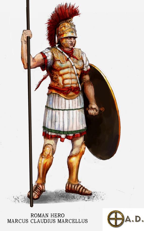
Some props like romans heroes are missing. we have Claudius Marcellus.

-
A good starting point would be adding the armour of the legs and trump in the elephant skin texture, and then do the armour of the right side of the texture with gold/bronze plating. Useful textures; binaries\data\mods\public\art\textures\skins\skeletal\maur_elephant_hero.png binaries\data\mods\public\art\textures\skins\skeletal\maur_elephant_siege.png References: Here are some tips in how to make textures in Blender by rendering!
-
Im very creative this night (-6 GTM) and I have restless ideas. I can't sleep. I want create Design Document only create art, 2D and try some 3D. my idea with inspiration by creative genius.
-
I open this topic to create with teammates props per icons related to technologies so to The community is open to participate. First Loom... @stanislas69 you can help ...:)