

DanW58
-
Posts
417 -
Joined
-
Last visited
-
Days Won
5
Posts posted by DanW58
-
-
MATERIAL TEXTURES REVISITED
Red_channel       5 bits   "color.dds"
Green_channel     5 bits        "
Blue_channel      5 bits        "
Alpha_test_ch     1 bit         "
FresnelGloss      5 bits   "optic.dds"
FilmThickness     5 bits        "
SurfacePurity     5 bits        "
MSpecularity      1 bit         "
Smoothness        8 bits   "smooth.dds"
I decided to forgo the idea of using fractional metallicity for rocks, and leave MSpec as a single bit channel, --"is_metal", in other words.
Single-bit channels are not too friendly to mipmapping and filtering, but on the other hand I can't think of an example where metal and non-metal would be finely mixed in a material, EXCEPT ROCKS ... But even in rocks, most metals appear as (optically) non-metallic oxides. I think we can postpone rocks. If worse comes to worst, we could conceivably have a separate shader for rocks and soils. Such a shader could produce the scintillation effect of grain of sand -sized chrystals with flat faces in random directions. I once saw a shader that simulated 8 randomly oriented tiny mirror surfaces per pixel, to give a metallized paint look. Even as I write this, it is becoming more and more clear to me that indeed, rocks and soils deserve a specialized shader.
So, as you see above, our material textures are settling nicely. Basically, we have two DDS textures 5+5+5+1 bits, and a monochrome 8-bit, all with mipmaps.
I think this it for now for our Material Textures package.
Next post I will deal with our Object Textures package.
-
 1
1
-
-
darn! I forgot to include a single-bit alpha-test channel. This is surprising: We need alpha testing for both materials AND objects. Why? For example, you could consider chicken wire fencing a "material" and use alpha-testing for the spaces between wires. Or you could make a whole set of tree-leaves into a material and apply this material to trees having big leaves made of it; but so the material needs alpha-testing. Whereas the object may need alpha testing for all sorts of reasons, windows, bullet-holes, you name it...
NOTE: Some readers might be alarmed by the number of textures being discussed. Keep in mind this is the full set, which in many cases may not be used. The only thing I ask, though, is that we use the same shader regardless of whether the object uses or not this texture or that. There should be in the game a folder for commonly used textures, and in this folder there should be a BLACK.PNG, WHITE.PNG, NONM.PNG (NO normal map, e.g 0.5, 0.5, 1.0 blue), etceteras, all 1x1 texel in size. When an object doesn't need a normal map, it just calls for NONM.PNG. Period! No need to change shaders for every combination of textures. If the oject doesn't need an emmissive texture, it calls BLACK.PNG. If it doesn't need an AO it calls GRAY50AO.PNG. Etceteras.
ANOTHER NOTE: I like clear terms. I like "smoothness" for specular power much more than I like roughness or glossiness. Roughness is the inverse of specular power, so it is counter-intuitive. Glossiness is a gross misnomer, as it has more to do with reflectivity than with surface geometry. Glossiness could be a good name for the Index of Refraction channel. "Smoothness" is PERFECT. Number two: "Metal" or "Specular"? Both can lead to confusion. How about "MSpec"? It has the advantage that you cannot assume you know what it is; you have to RTFM. Number three: Indeed I really want to use "glossiness" for Index of Refraction, but the imbeciles took it over...
 If I use it for IOR, now, it will confuse people familiar with the bad systems. darn! ... Well, FARK THEM! "Gloss" it is. NOT "Glossiness"; just "Gloss"
  That will be the name for IOR. (And for anyone about to argue the term, consider this: You go to the paint store and see a can of "high gloss" varnish. Does that mean that the surface will be very flat? No, the surface will be as flat as you paint it. It means it has a top of the range index of refraction, so it reflects a lot. So I'm not being harsh calling them imbeciles; they ARE TOTAL imbeciles, twisting the meaning of words --deliberately, probably, just to look authoritative and powerful by twisting words AND getting away with it; as well as to mesmerize and confuse and be pretentious.)
One thing that looking at that tlGF stuff reminded me of is that multi-channel textures exist. We only have one UV coordinate for material, and one UV coordinate for AO, per fragment shader execution, so it is a bit wasteful to have so many separate texture fetches. If we packed all 8 material channels in one texture, and all 8 object channels in another (AO, normalmap, etc), we could have just two texture fetches (in addition to environment map fetches, of course). That might have better performance. I've never used multi-layer textures, however; I have no idea with regards to their support by older hardware... It shouldn't be too bad, though, as I remember these types of double decker whooper textures existed when I was in this business 20 years ago. But for now I will try to proceed as if I'm targeting a bunch of standard texture formats.
In any case, some angles we must look at before moving forward too fast are the precision, dynamic range and mipmap concerns for each of the channels.
MIPMAPS:
(For those who may not know what mip-maps are: These are like a set of smaller textures packed together with a texture, where each is half the size of the previous. Imagine you take your image in GIMP and scale it 50% and save under a new name; then scale again 50% and save under another name, until you get to a 1x1 texture, then package all those scalings in one file. At game-time, if you zoom out or move away from an object, pixels on the screen would fall on multi-texel strides on the texture, which would introduce aliasing problems, so you pick the the level of scaling that gives you a stride of 1 texel. Or rather, you pick the two scalings with the closest to 1 texel strides, and interpolate between them, as well as in the U and V directions in the texture, which is why this technique is called tri-linear filtering.)
Having said that, mipmaps sometimes cause artifacts, rather than prevent them. Just to give you a simple example, normalmaps are kind of infamous vis-a-vis mip-mapping and filtering artifacts. Ambient occlusion isn't negatively impacted by mipmapping at all, but it doesn't always benefit from it, either. Height map (for parallax) can suffer disastrously from mipmapping...
Notice a pattern? It seems like all the textures in our Object Textures set are mip-map un-friendly, or at least mip-map skeptical ... Perhaps it's worth considering NOT having mipmaps for Object textures; but stick to bi-linear filtering for them. Food for thought...
I can't think of any of the material channels having any serious problems with mip-mapping, on the other hand. Can you?
DYNAMIC RANGE:
I don't mean HDRI here. Color channels are all 0~1; no material can be albedo of 2. HDRI deals with dynamic range of LIGHT; here we are dealing with MATERIALS.
Big difference.
The dynamic ranges to consider are for such parameters that need to be mapped to a 0.0~1.0 range. So, it does not apply to red, green or blue. It does not apply to a "boolean" such as "is_metal". It does not apply to the "surface purity" channel, which goes from pure diffuse (0.0 purity), to pure dielectric specularity (1.0 purity).
It does, however, apply to...
Gloss, our term for Index of Refraction. This is going to be a hard choice here, though... Indexes of refraction for materials go, PRACTICALLY, from 1 to 3. Anything outside this range is for SciFi really. But there are exceptions. Some people argue that metals have negative indices of refraction. If we were to take that at heart, we'd get rid of the MSpec channel, and have Gloss extend down to -1.0. I'm not sure what results we'd get. But it is not a good choice because metals can have a passivated oxide layer that acts as a non-metal, having a positive IOR, of some given thickness; and a negative IOR to represent metal would then be unable to represent metals with transparent oxide surface layers. So the bottom of the range for IOR is 1.0, same IOR as for air and vacuum. Water is 1.5. Glass is 1.5 also, which is why it is so hard to see a piece of glass under water. I think diamond is 2. I heard some materials going a little over 3.0. Then again, there are some laboratory made materials with IOR's as high as 7, or so I've heard. I think that in the interest of simplicity and compromise (and peace) I'm going to set the range to 1.0~5.0, mapped to 0.0~1.0. Thus,
IOR = ( Gloss * 4.0 ) + 1.0
Gloss = clamp( ( IOR - 1.0 ) / 4.0, 0.0, 1.0 )
I don't thing Gloss will need too many bits of precision, however, for two reasons: Variations in IOR in a material would not be too apparently noticeable, and they don't often occur, whether naturally or artificially.
Thickness of passivated layer, for rainbow tinted specularities, I would tentatively say that the range of interest is up to 10 to 20 wavelengths of red light. 650nm x 10 = 6500nm = 6.5 microns. So, from 6.5 to 13 microns. More than that thickness we get into a range where the rainbow tint cycles would cycle too fast with changing angle to even notice. So, tentatively I say 0 to 10 microns maps in 0.0~1.0 range.
You may be wondering why we need a channel for thickness of this passivated oxide layer. We do because whenever you see such rainbow reflections they seem to proceed at different speeds, slowly near areas without the effect, faster away from them; and to produce a realistic effect we'd have to make it do something similar. So, if you are modelling a magical sword made by Indra, you might give it a thick layer on the sides, but thinning towards the edge, and with multiple thinning blobs along the length, and blurred the heck out of, for good measure. This should result in fine bands of rainbow color on the sides (as you turn the sword in reflecting a light), slowing to wide and less changing color bands towards the sharp edge and blobs.
Smoothness is a very special case, because here we need to map a range from zero to infinity with a miserable 8 bits of precision. I tackled this in some other thread and came to the conclusion that a pretty good mapping would be one minus the inverse of the fourth root of specular power. Let's try it to see if it works:
To texture: Smoothness = 1.0 - 1.0 / sqrt( sqrt( SpecularPower ) )
From texture: SpecularPower = pow( 1.0 / ( 1.0 - Smoothness ), 4.0 )
So, an encoding of 255 for maximum smoothness comes to... 1-255/256 = 1/256; 1/(1/256) = 256; 256^4 = 64k^2 = Too much.
In fact, the highest specular power we could ever need is 65000, as that is the specular power that represents a sun reflection of the right diameter, if the sun is modeled as a point source, as per the calculations at the bottom of the first post in this forum thread. So I'm going to change the formula to just a square, instead of a fourth power.
To texture:  Smoothness = 1.0 - 1.0 / sqrt( SpecularPower ))

From texture:  SpecularPower = pow( 1.0 / ( 1.0 - Smoothness ), 2.0 )
This channel, however, is probably THE most precision-sensitive channel in the whole package.
PRECISION (OR RESOLUTION):
For RGB, I defer to the designers of the DDS texture format(s). 5,6,5 bits, or whatever they did, is fine with me. Color is overrated, anyways.
Alpha testing by definition needs only 1 bit.
MSpec would probably do well with as little as 5 bits.
Gloss would probably do well with as little as 5 bits.
Purity would probably do well with as little as 5 bits.
Thickness of passivated layer would probably do well with as little as 5 bits.
Smoothness, OTOH, needs a full 8 bits.
Ambient occlusion needs a full 8 bits.
Normalmap also needs 8 bits, but we could save the W channel; it can be calculated by the shader from U and V.
Emissive would probably do well with as little as 5 bits.
Faction color, decal and logo would do with 1 bit each.
In the next post I'm going to summarize all this in a table.
-
1
-
-
@hyperion I think you missed my last post.
-
1 hour ago, Stan` said:
What is that ?
JPL = Jet Propulsion Laboratory; the Production department of NASA. They have a habit of making super-long acronyms for spacecraft, etc.
1 hour ago, Stan` said:Just meant a lot of. (also we have a 32768 limit of vertices per mesh) mostly say below 10k but sometimes artists happen
Gottcha. Yeah, that's why I said "one level of division" would probably not affect it. Two is a different story.
The 32k limit per mesh is actually quite common; just the fact that a 16-bit index can only address 64k objects, minus one bit for special things probably. If you wanted to get rid of the limit, all indexes would have to be 32-bits, which is quite a jump. And you can't have 20-bit. Nothing to do with performance, anyhow.
-
So, having said all that, let's get to work. Thanks to analyzing glTF's absurdities, I now have a more clear view of the path ahead.
Texture channels need to be separated into two distinct groups:
MATERIAL TEXTURES
Material textures are what defines a material, irrespective of where it is used, irrespective of lighting conditions, irrespective of whether there's a bump on its surface, regardless of whether a blow torch is heating a portion of it and making it glow red. All the material textures care about is the representation of a material, and should include at least the following eight channels:
- Red
- Green
- Blue
- Specularity (metallic)
- Smoothness (gloss or ANTI-roughness)
- Index of refraction
- Purity of surface layer
- Thickness of refractive layer (for rainbow tinted metallic reflections through passivated oxide layers)
OBJECT TEXTURES
Object textures are what defines an object's appearance other than material. Object textures should be material-independent to the extent that you could completely change the material(s) an object is made of and NOT have to even touch the object textures at all. Here are 7 to 9 channels to consider
- Ambient Occlusion
- Normal U
- Normal V
- Normal W
- Height (for parallax)
- Emissive texture (incident light, rather; NOT material-modulated)
- Faction Color Map
- Decals and Logos (option to consider)
- Damage (option to consider)
UNDECIDED:
There's one channel I've been mentioning, Detail Texture Modulation, which I'm now on the fence whether it should be material-oriented or object oriented...
Nah, 1 minute of thinking did it. Object. Why? Because material textures can have unlimited detail due to the freedom to overlap UV islands. Where detail is at a premium is in the second UV set. So adding this as number 7.
EDIT: And even if we considered having detail textures for materials, which we can still do, it would probably not be necessary to modulate them.
OBJECT TEXTURES (revised)
Object textures are what defines an object's appearance other than material. Object textures should be material-independent to the extent that you could completely change the material(s) an object is made of and NOT have to even touch the object textures at all. Here are 8 to 10 channels to consider:
- Ambient Occlusion
- Normal U
- Normal V
- Normal W
- Height (for parallax)
- Emissive texture (incident light, rather; NOT material-modulated)
- Detail texture modulation
- Faction Color Map
- Decals and Logos (option to consider)
- Damage (option to consider)
EDIT: Another thing to consider, for materials, is generative textures. Some algorithms can produce 3D textures, such that you could cut a stone and find what the texture looks like inside. Not much use for this in 0ad, but worth keeping in mind for future expansion in use of the engine.
-
1
-
Hyperion, I'm not insisting we do things differently, necessarily. I just want to establish requirements first; even design a packing in full detail; THEN compare to other solutions. I like to think things through from first principles, just like Elon Musk; I don't assume others know better than me. Sometimes it is the case; but I like to discover it, rather than assume it. If I'm going to sit on Disney's shoulder, I want to know EXACTLY what advantage it's going to give me. Am I going to get free scripts that generate all the textures, which otherwise I will have to write my own? Or is it compatibility with rock and stone libraries that go for $50 a virtual bag, when I can get real stone at Dollarama for $1.25?
QuoteThe best paths to export a glTF right now are Substance Painter, Blender, and Autodesk 3ds Max. Since we were just looking at creating textures for glTF in Substance Painter, we will start there.
I don't have Substance Painter, or 3ds Max.
So all I'm asking is let me go at this the long but sure way. Think it through in detail. Afterwards we compare to something else and figure out if we should go with that instead. I'm frankly tired of hearing about this and that being the ultimate crap sort of marketing, which often amount to 1.5 good ideas under the hood, and a dozen new problems. In electronics, there was the EDA revolution in CAD systems, with probably several million hours of sales teams going around manufacturers to explain what a marvelous new thing EDA was, and the entire world jumped on it, and all the CAD companies became repeaters of the EDA mantra, and here we are today, CAD systems are the same they always was; EDA was complete vapor-ware. There was ISO-9000 and how it was going to revolutionize industry with deep, company wide quality philosophy, and where does it all stand? Companies have to rush once a year to "put something together to show the ISO guy when he comes". Just a huge pile of hogwash.
The only effect of these "revolutions" is to actually prevent evolution in the very direction they claim to promote it. In the case of ISO-9000, for example, it prevents good documentation practices. Twice in my career I tried to implement a GOOD documentation system (I do have a working definition) but was told that whatever I did could not conflict with ISO-9000's (dictatorial) ways.
I was writing software, at one time, to automate going between parts-lists from my CAD tool and stock control, and was told it was not necessary since the tools coming soon would have EDA and automate all that... Never happened.
In this case it may have happened already; but I want to see if the solution is exactly right, or not. And if it isn't exactly right, is there enough advantage in following them to offset the lack(s) or shortcoming(s)? But if you want me to NOT think, just blindly follow, it is not going to work. I've never been, and never will be, a blind follower; and appeal to authority does not appeal to me.
EDIT: I'm reading through the page you linked, trying to understand where they are at. One thing that strikes me already is the poor writing, such as "The format does expect the textures in a specific format". It says that base color, normal and emission are saved as individual files, but does not explain why. It insinuates it is due to precision, saying they are PNG, but I can't imagine color or emission are so sensitive to compression. Normalmap yes...
QuoteTexture Requirements
The glTF format supports the following textures for the Metallic-Roughness PBR model:
- Base Color
- Metallic
- Roughness
- Normal
- Ambient Occlusion
- Emission
The format does expect the textures in a specific format, however. The Base Color, Normal, and Emission textures are saved as individual files, preferably a PNG as the format is lossless. The Ambient Occlusion, Roughness, and Metallic textures are saved in a single channel-packed texture to reduce the number of texture loads. The textures need to be packed into the channels of your texture as follows:
- Red: Ambient Occlusion
- Green: Roughness
- Blue: Metallic
Going forward, I will refer to this channel-packed texture as the ORM texture for Occlusion, Roughness, and Metallic.
So, if I try to piece together this steaming pile of confusion, they basically have the same thing I was suggesting as far as a single RGB for diffuse or specular, controlled by a fourth channel, call it "metal" or "specular", matters not.
Then roughness (or gloss) ((or as that game developer suggested SHOULD have been named, "smoothness")) is the specular power. PERIOD.
Now, @hyperion , here is the crux of the matter and why we cannot use their solution. Why, in fact, it is poorly thought out:
We have two UV layouts in the models. A great idea.
1) The first is for material textures that are shared game-wide. In this layout, islands of unwrap can be freely overlapped, increasing efficiency.
2) The second is for ambient occlusion, where not so much resolution and detail are needed, but the UV islands MUST NOT overlap each other. I presume this second UV layout is the one to use also for normalmap, as well as for the emissive texture. ALL of these must be unique, non-overlapping.
If Disney, or whoever came up with this glTF would have spent some time THINKING, they would have realized that all material related files, and all non-material related files, should be kept separate. Thus, you would pack color, metal and roughness in one texture; and ambient occlusion, normal and emission in another. Instead, they mixed things from these two domains randomly: "The Ambient Occlusion, Roughness, and Metallic textures are saved in a single channel-packed texture".
And where is the Index of Refraction?
This is retarded.
In any case, we cannot use it, as our ambient occlusion is in a separate UV.
EDIT: This is the only reference I can find so far on the metal/roghness/spec/gloss being anything but semantics:
QuoteThe biggest different though is in the usage and why the naming is important.
Glossiness 0=not glossy, 1=glossy
Roughness 0=not rough(glossy), 1=rough (glossy)
Specular is a not well defined process, you can use it to change specular colour and intensity
Metallness is quite different from specular colour in that it defines where the specular colour inherits from the underlying albedo where the intensity is a function of the energy conservation of PBRWhich is clear as mud to me. So "Metallness [sic] defines where the specular color inherits from the underlying albedo", eh? So where is the texture for undelying albedo? And where in physics does specularity need to "inherit" anything? If anything, albedo should inherit from specularity. When you speak of the albedo of a comet or asteroid, it combines diffuse and specular. Diffuse inherits from specular, in a physical sense, as it is a power of specular color, given multiple bounces. And albedo inherits from diffuse AND specular, by combining them. So here is someone who has no idea what he is saying, pretending to explain the unexplainable, and only going half way... What about specular?
-
1
-
4 hours ago, Stan` said:
I think I said it before but I'm really worried about how it will look with uneven terrain. Can you check?
darn! I just understood what you're talking about. The wall extensions. They will be exposed, but seem shadowed.
Here's a simple solution: Instead of at ground level, place the ground box down to the end of the wall extensions; and either make it larger or perhaps make it circular and add a wall or rim at the edge that goes up to ground level. The wall's downwards extensions will get progressively darker as they go down, but by very little. I'll make a prop that can be imported and used for this.
Here we go:
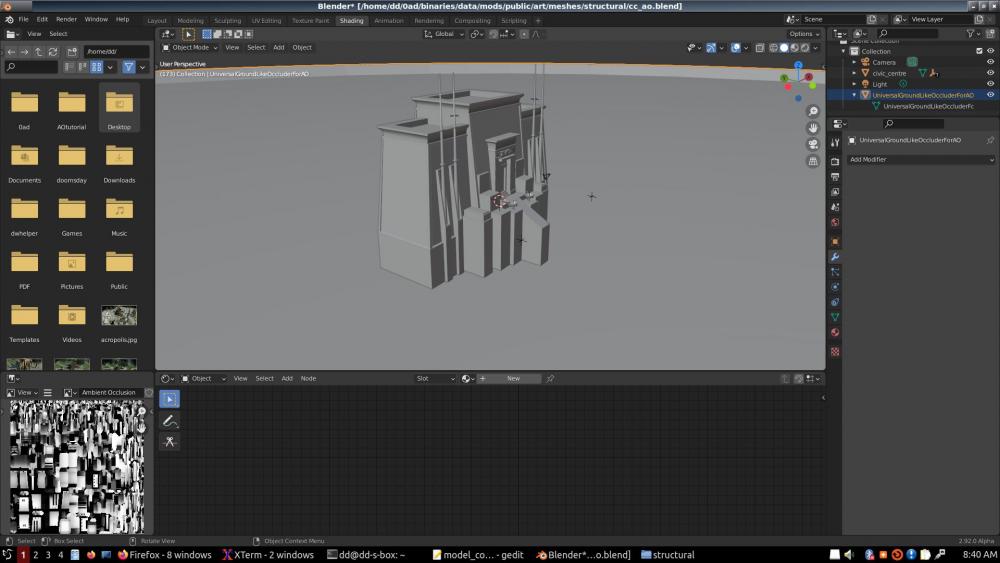
Mesh attached at the bottom. UGLOFAO stands for Universal Ground-Like Occluder For Ambient Occlusion.
(I should work for JPL...)
4 hours ago, Stan` said:Oh I think I remember that option now. We didn't use it cause it make buildings look out of place with the current material values.
This is a perferct example why I'm such a non-believer in "tweaking" things. If it should be right, but doesn't look right, there's a problem to investigate. But if you guys didn't know what Normalized was for, or why an AO should always be normalized, that explains things. But generally, tweaks, like the gains set to arbitrary numbers in the xml files, will sooner or later come back to bite you. Not only that; tweaks also reproduce like mice. You tweak one thing today, and tomorrow you have to tweak a dozen other things so they don't disagree with the tweaking of the first... Let's go to physics and optics from now on. Taste arguments can't resolve; but physics and optics are science.
4 hours ago, Stan` said:Strong subdivision might increase overdraw
What's "strong subdivision"? Never heard the term.
-
2 minutes ago, wowgetoffyourcellphone said:
You can certainly intersperse text and images on the forum. I do it all the time.
I've no money to offer for the knowledge, I'm afraid.
 I therefor beg for it; how do you do it?
I go to edit and I see a bunch of square icons representing the images. Nowhere to place a cursor between any icons.
-
I've no idea how...
-
1 hour ago, Stan` said:
Thank for making a tutorial. So basically it's AO without any extra options and a ground plane
Right. Well, I'm not sure what you mean by extra options, so I can't opine yet.
It's AO with a ground plane, for sure.
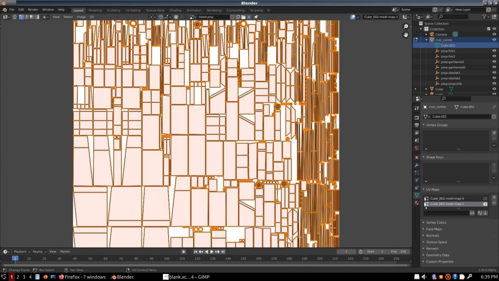
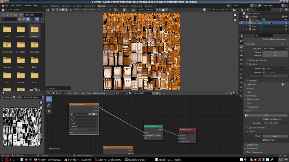
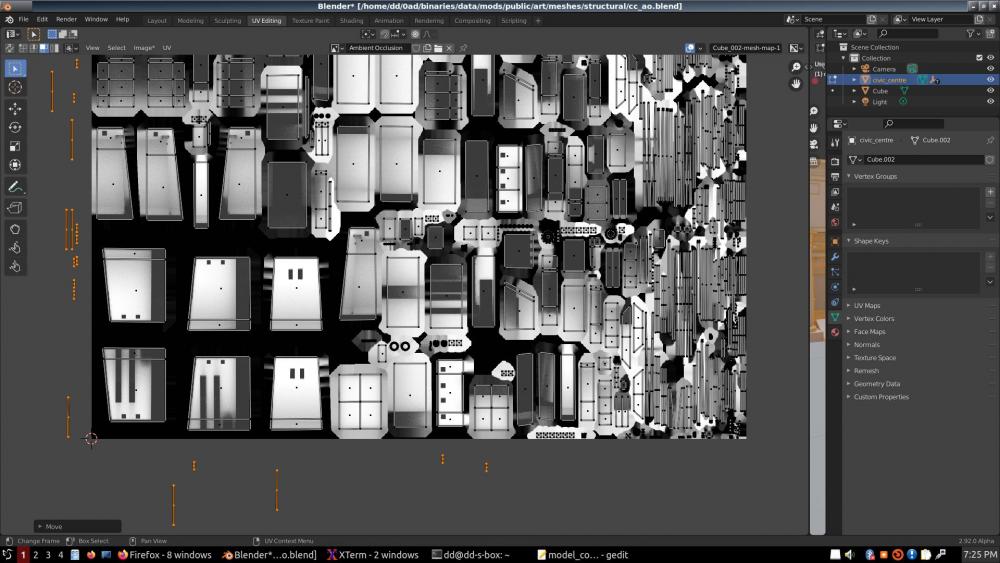
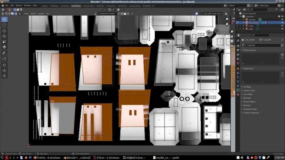
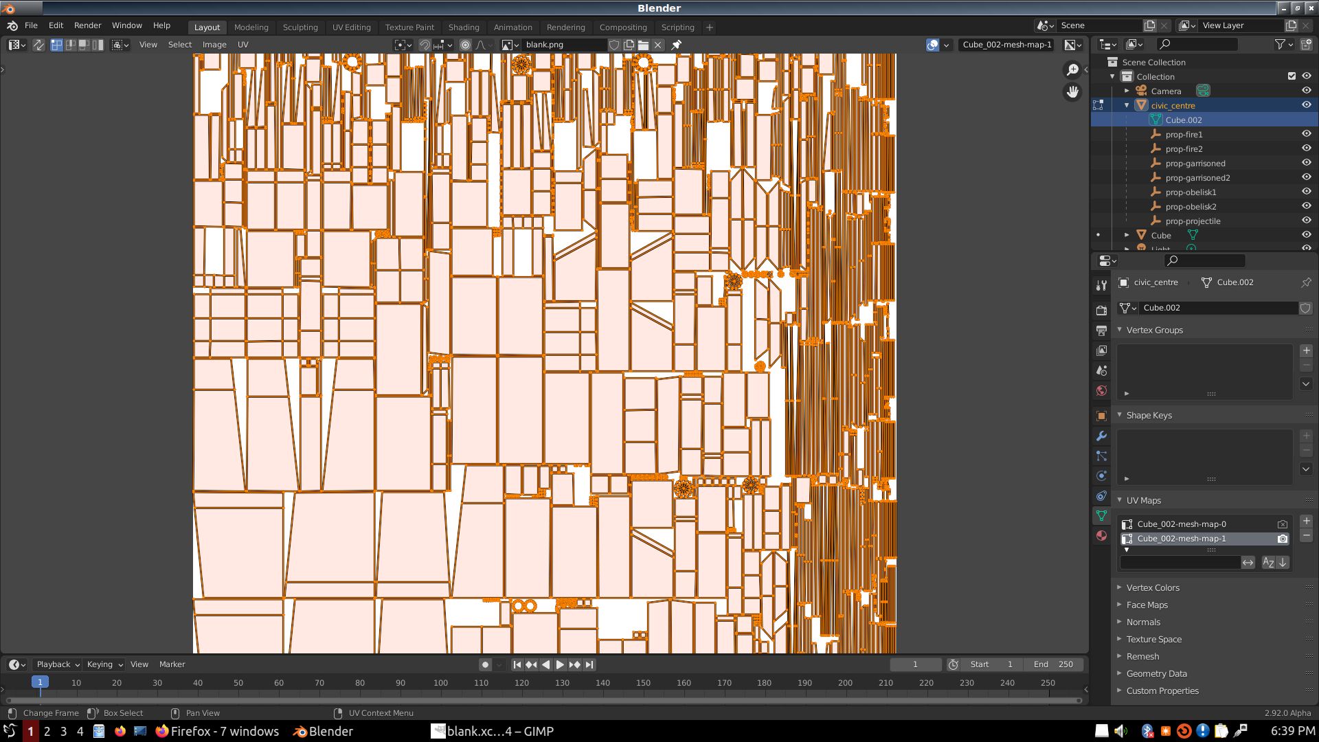
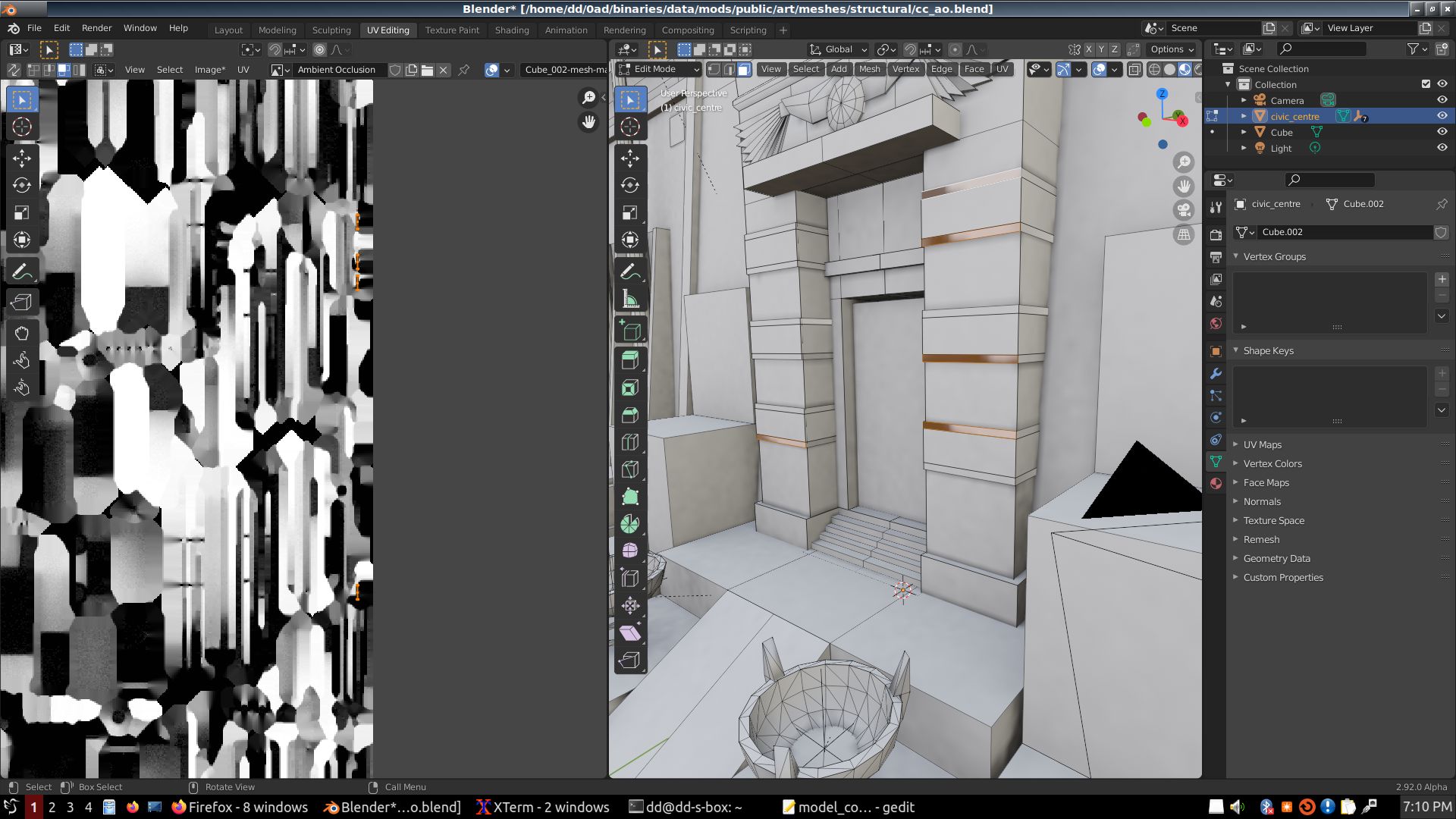
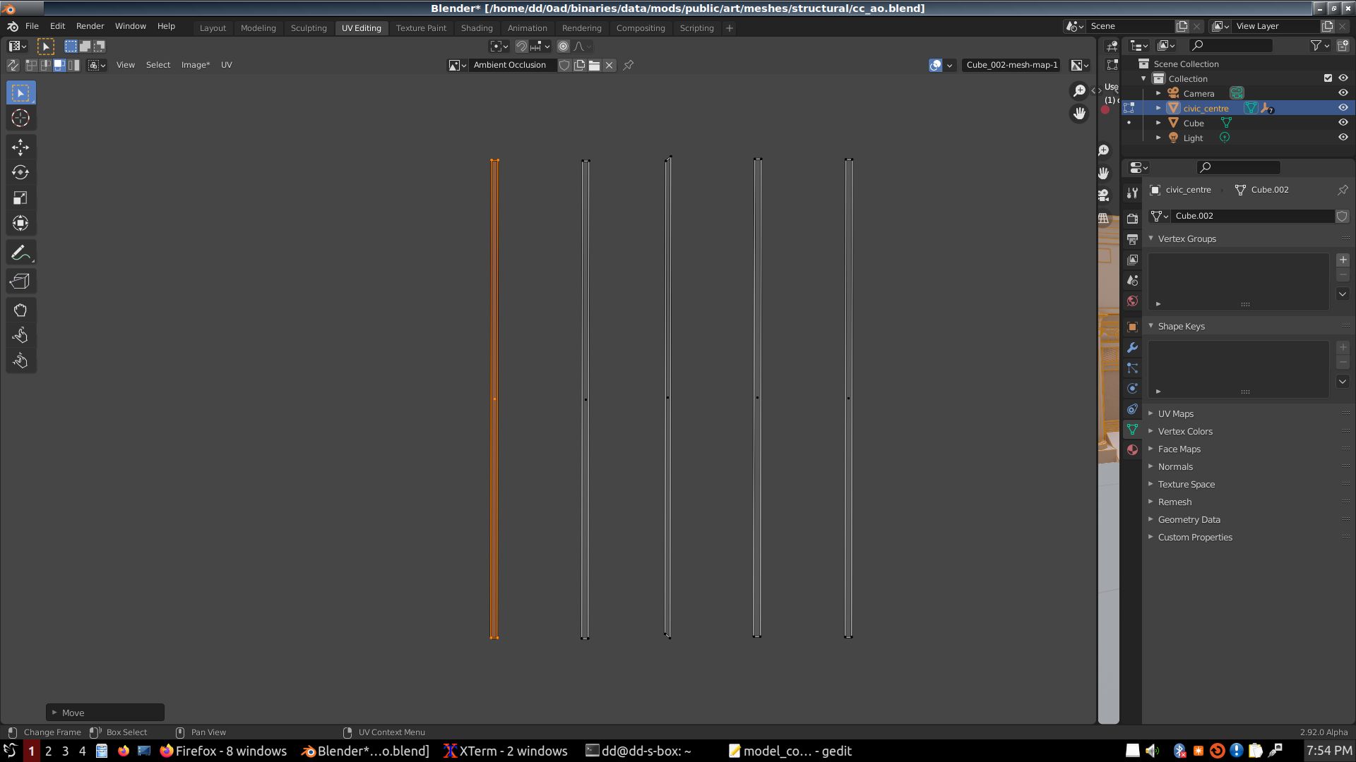
Increasing space between islands... VERY IMPORTANT. The islands in this model were JAM-PACKED like sardines in a can. NOT good!!!
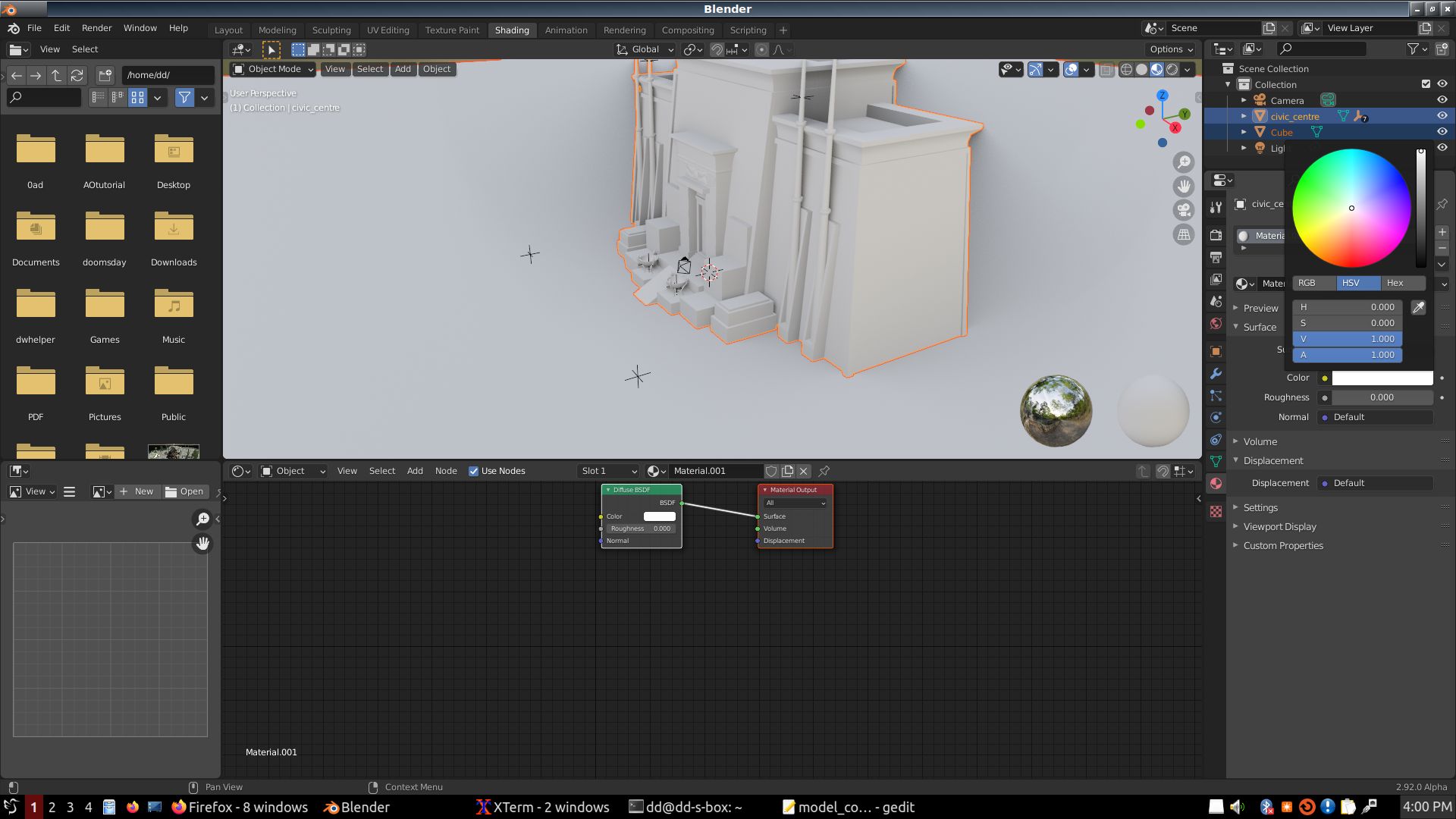
NOTE: The problem I discovered with existing AO's of them being too dark; no part of the texture looking brighter than 0.63, didn't manifest for me. There was no "Normalized" button like there used to be in older Blender versions; but what came out was normalized anyways. I'm not sure why the current AO's are so dark. One thing I did was I set the material to 1,1,1 white (default is darker). Not sure AO should even look at material, but I just throw that in.
Yeah, well, poly-count is overrated. Even if indeed the Pyrogenesis engine is CPU bound, the days when CPU's were so slow that poly-count was all that mattered are LONG gone; I'd say today you could add one level of subdivision to everything, and it would not make a difference at all. Your devs should try this as an experiment. Whereas overdraw is a GPU KILLER. I'd cut off all the junk inside the building and weld together everything that's left, and I bet you ANY MONEY (including Bitcoin) it will improve display time.
-
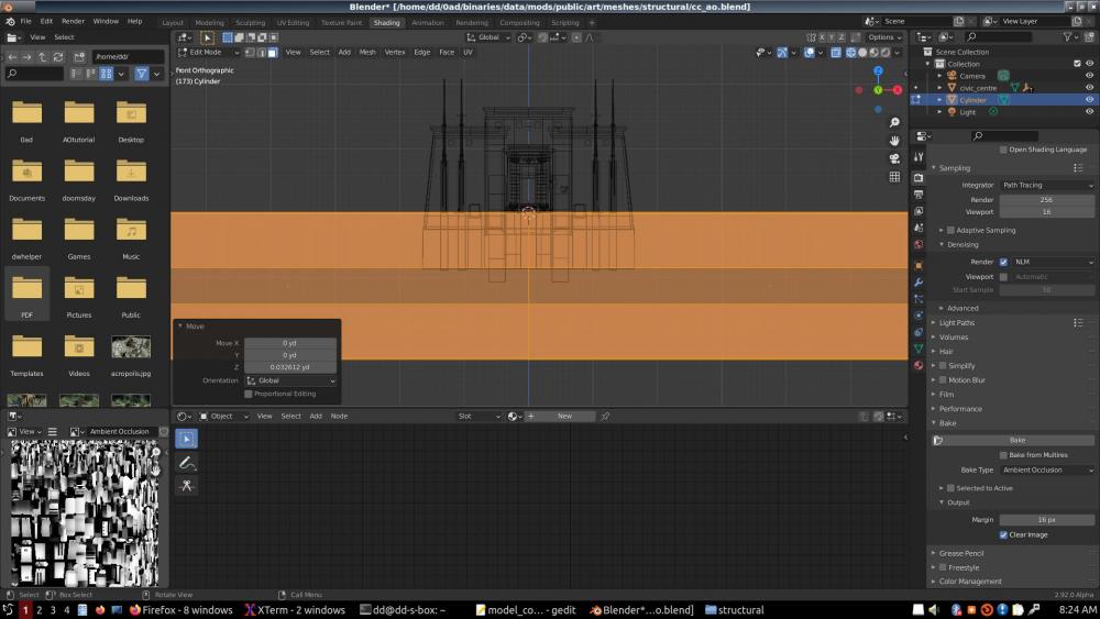
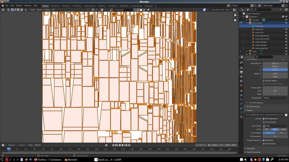
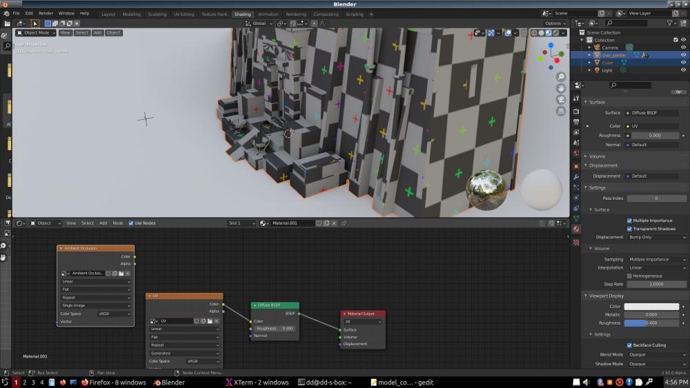
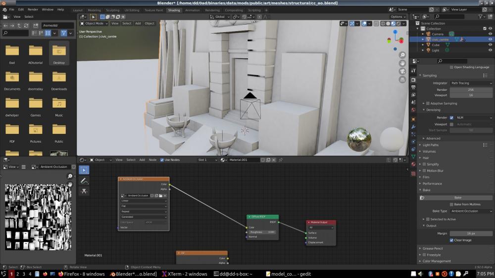
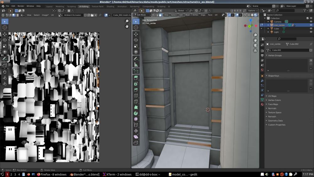
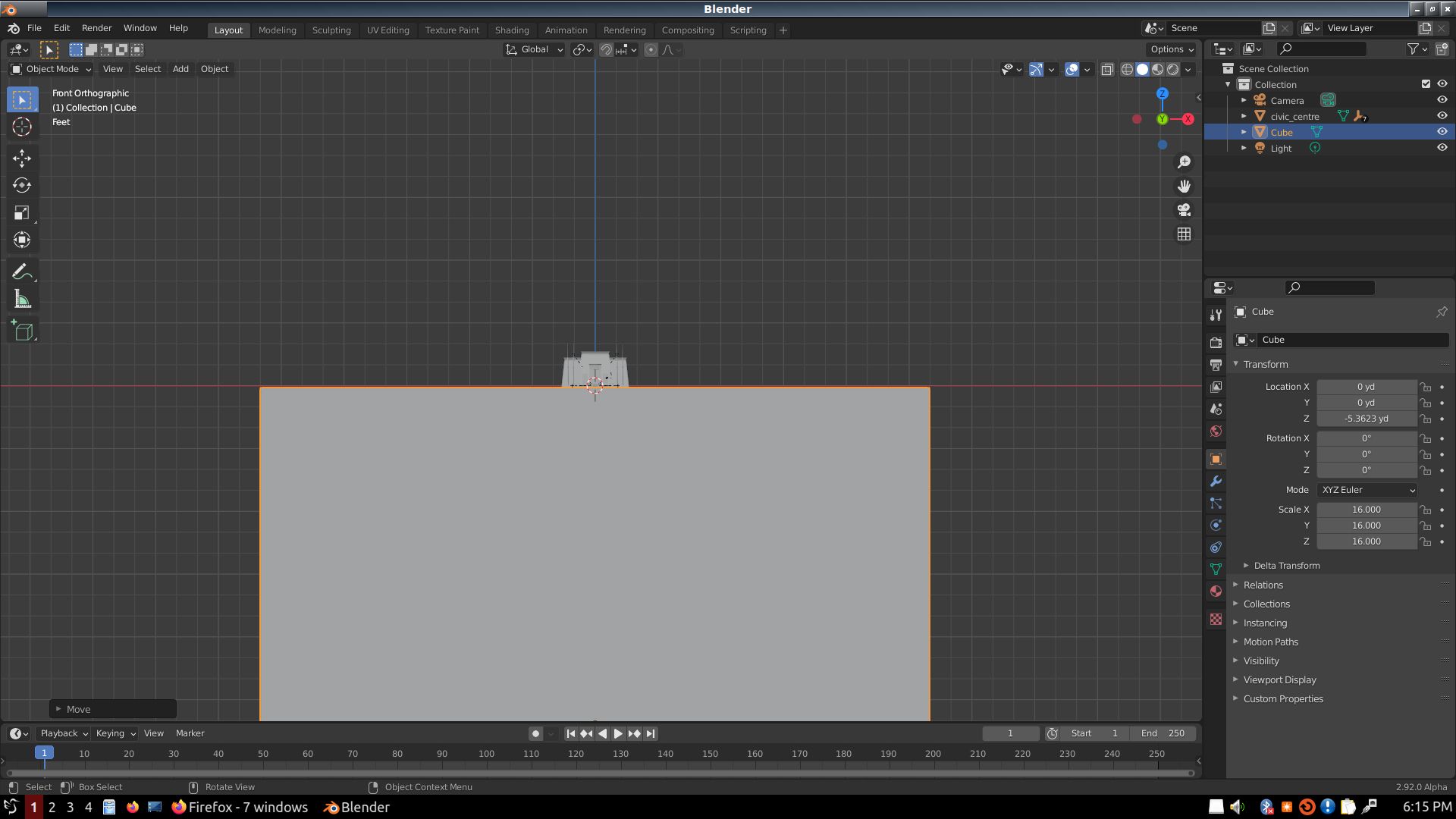
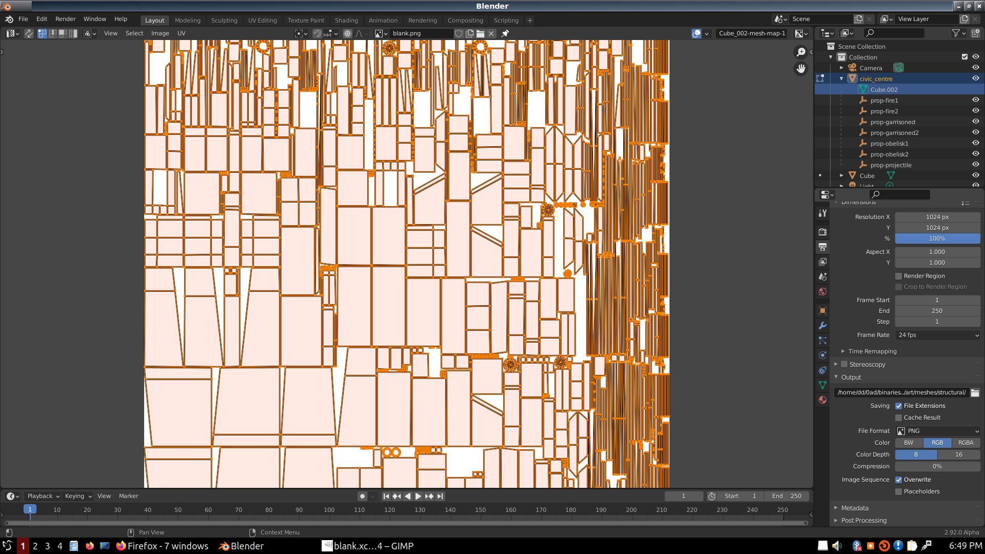
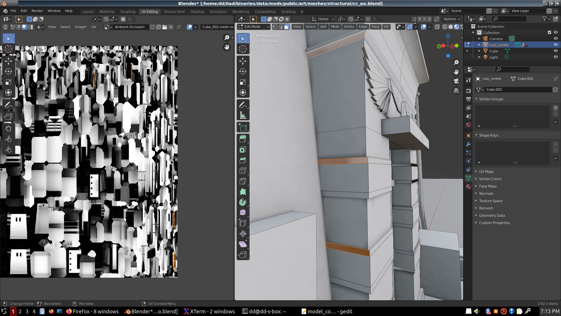
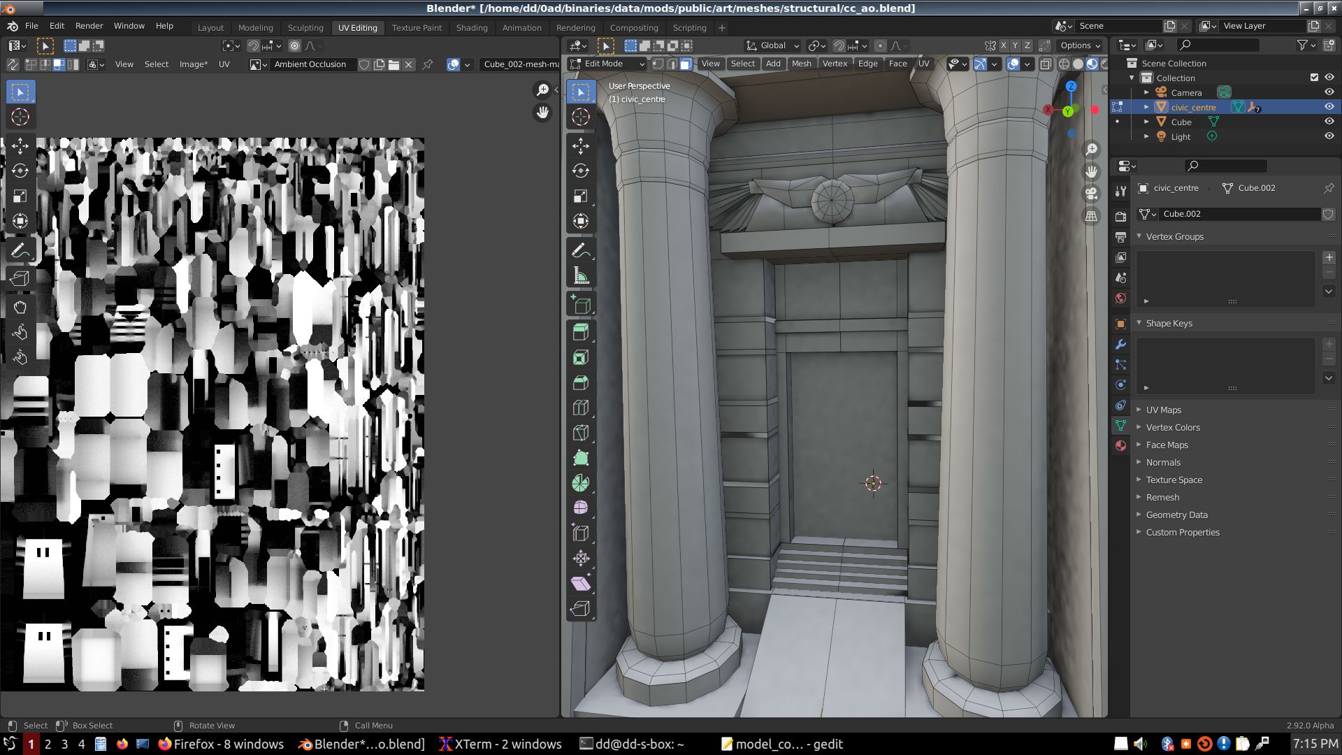
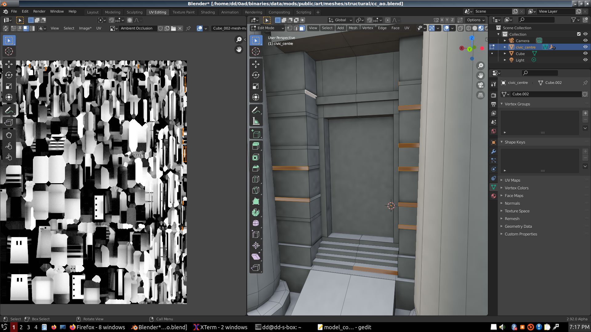
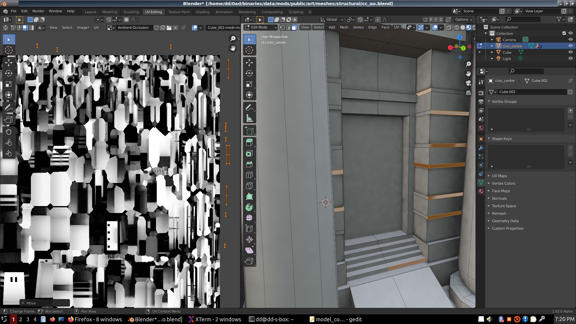
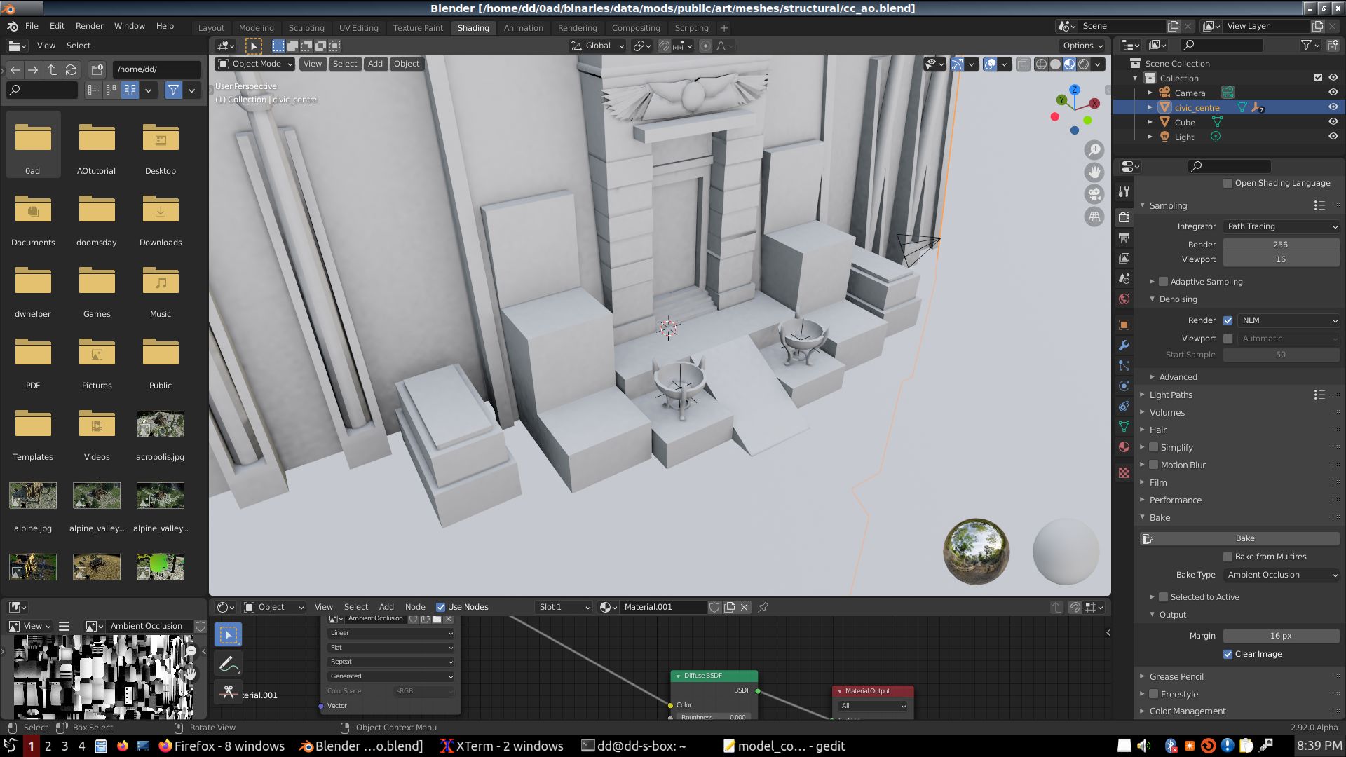
Ok, in lieu of a properly formatted tutorial, here's a rough outline of what the image sequence is about:
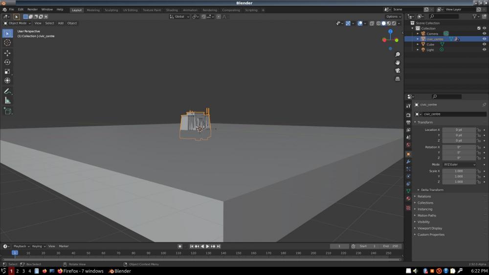
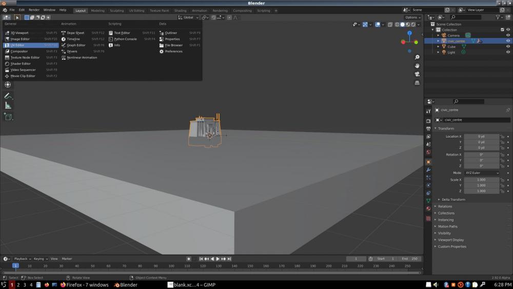
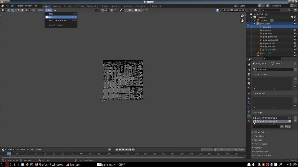
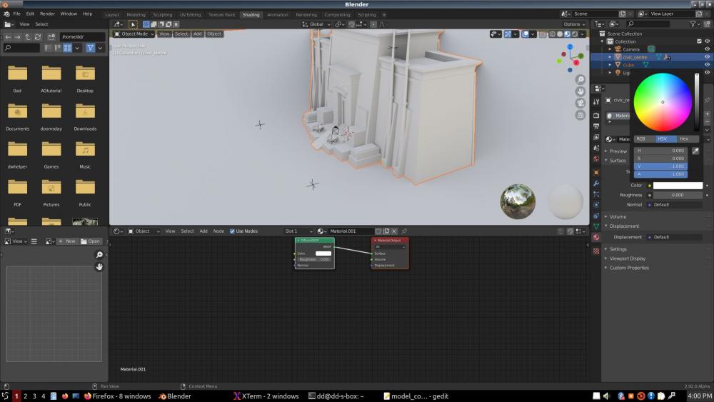
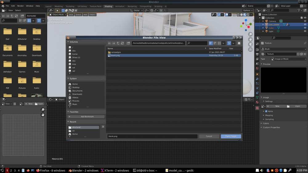
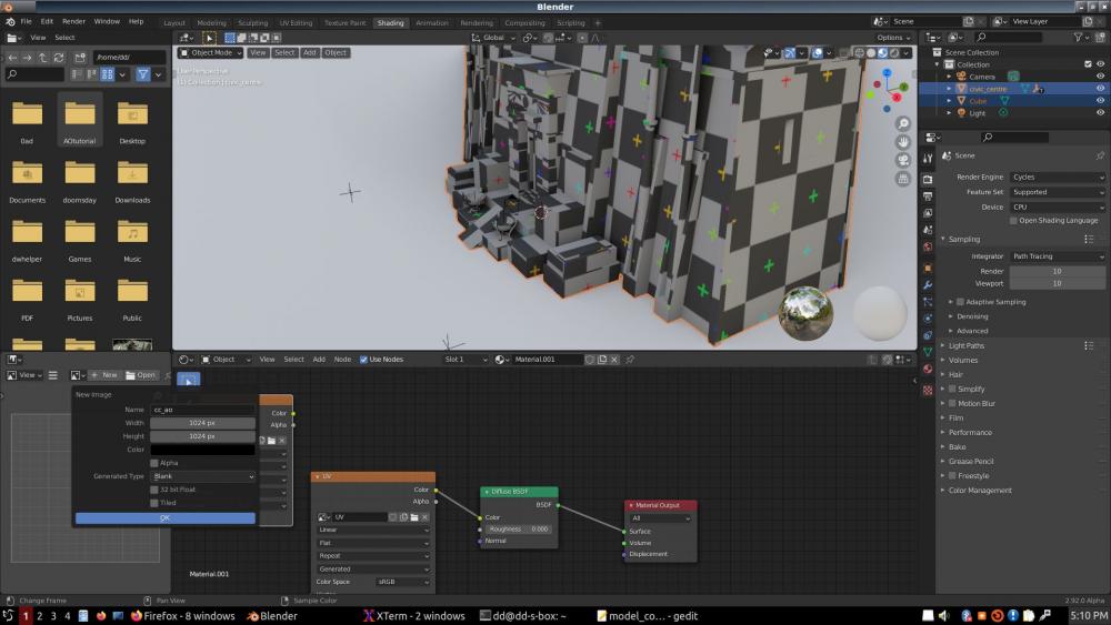
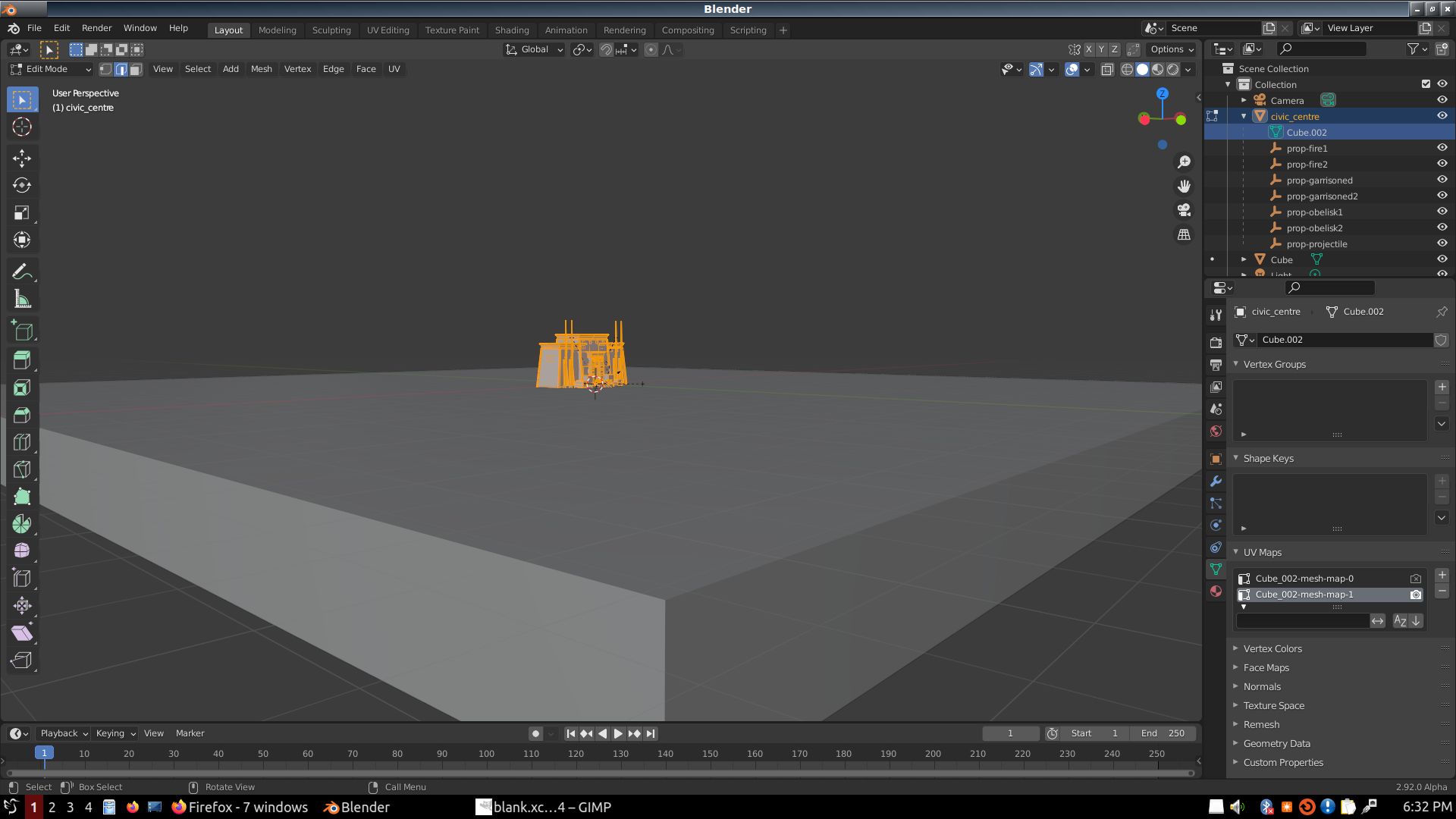
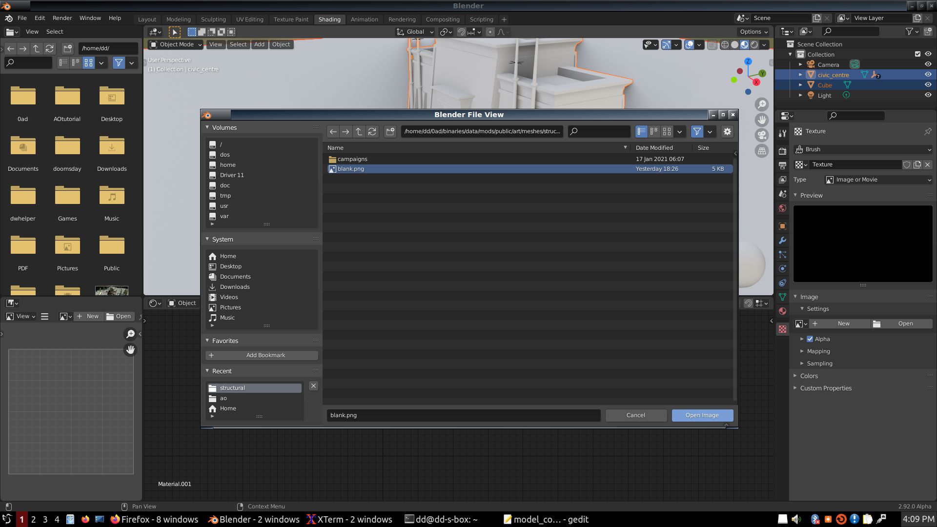
After loading the civic center, I went to UV mode to slap a blank texture on it. I don't know if this is necessary; probably not; it was the way it used to be in Blender.
The images are really a chronicle of my journey to getting to bake an AO like 80%; the other 20% is tutorial.
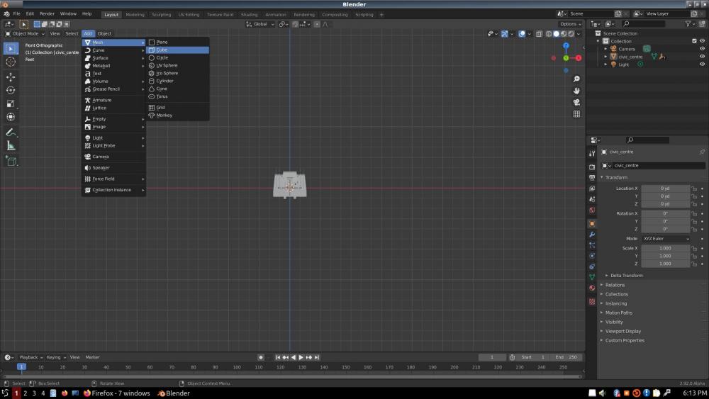
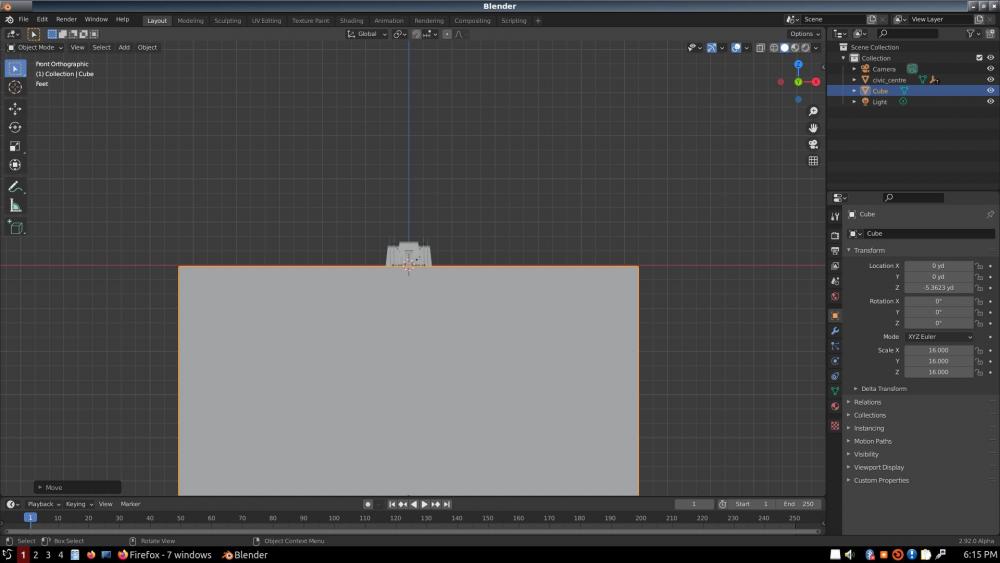
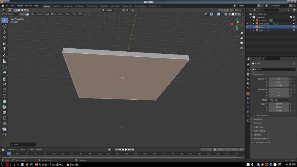
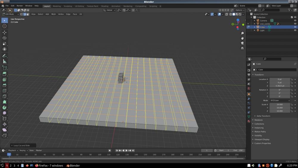
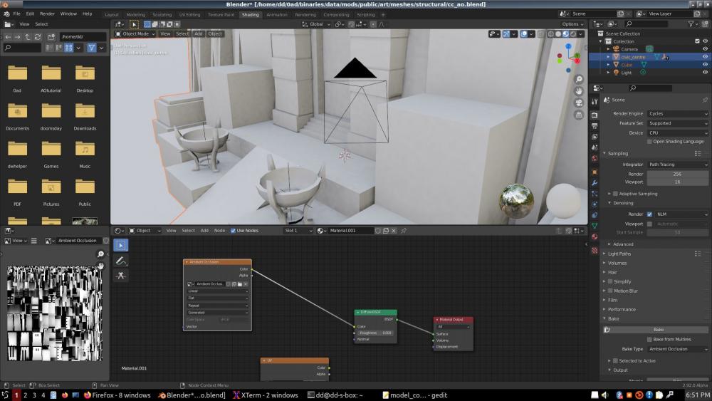
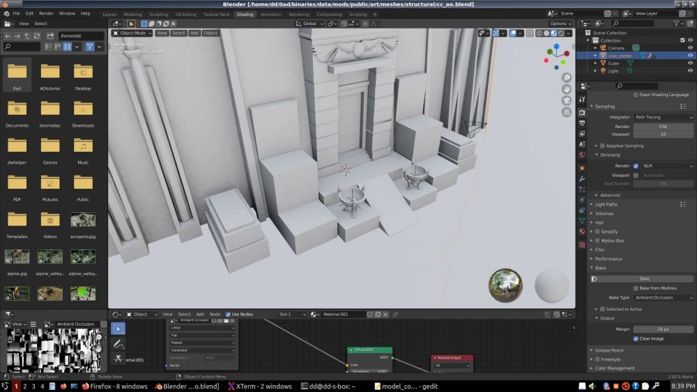
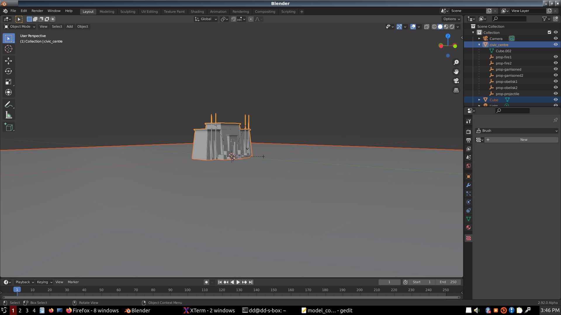
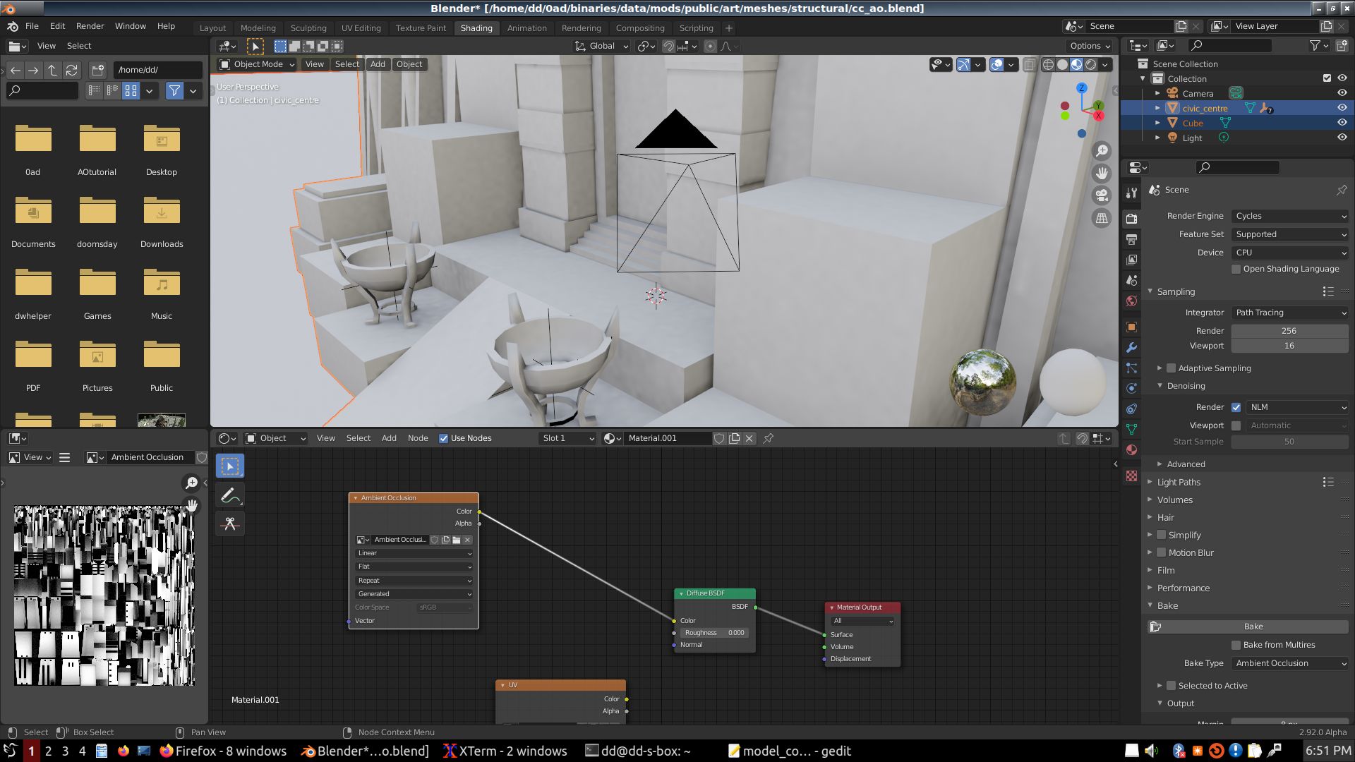
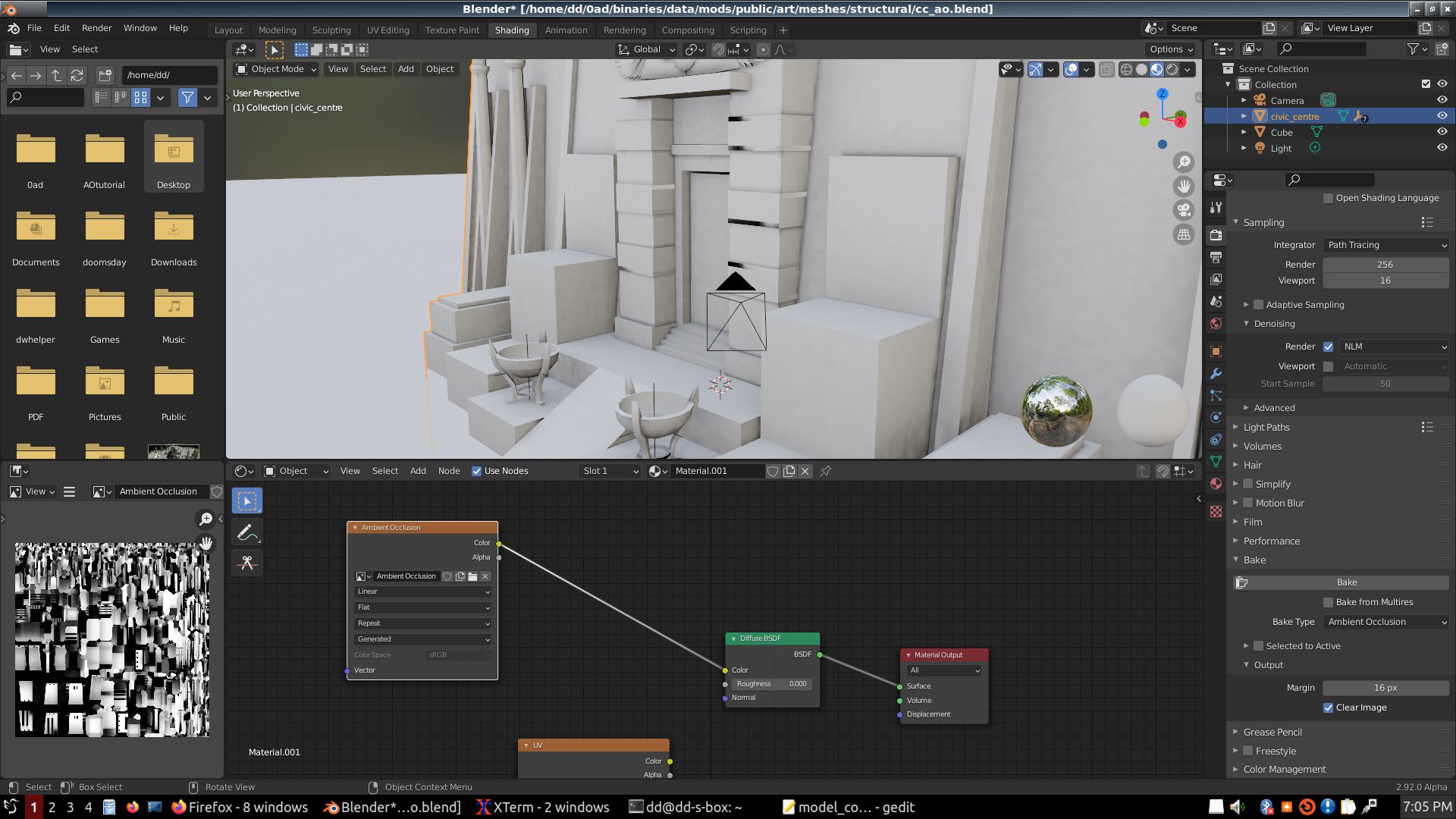
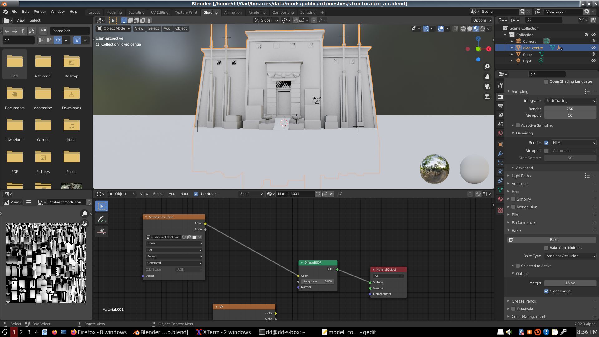
One thing that IS tutorial material is when I place a big cube so that the top-side is at ground-level relative to the cc.
Then I raise the bottom of this cube to a reasonable depth; we don't need to reach the center of Earth to block light...
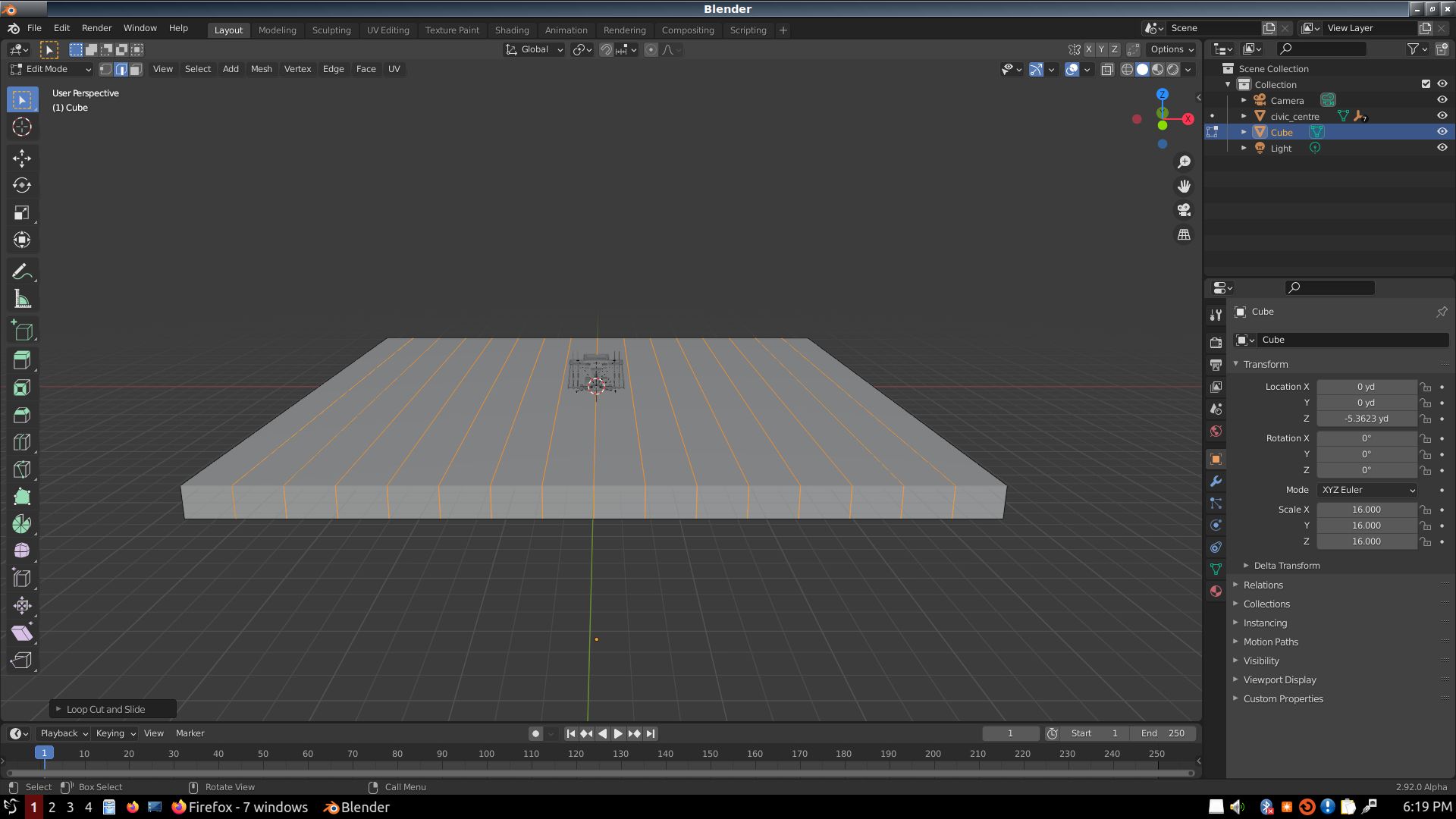
Then I used Ctrl-R 15 to divide X and Y of this cube into 16 strips. This is important to reduce possible errors by Blender if the occluder is so big the edges of the occluding polygon are outside the range of what Blender is looking at. Very large surfaces are often sources of artifacts.
The box is only there for the baking, then it is thrown away; deleted permanently for all I care. It prevents light coming from underground affecting the AO. Usually, buildings don't float in space; except in SciFi; and so they get most of the ambient light coming from above, down to the horizon, but not from below the horizon (except for light reflecting off the ground, but we can't compute that light for AO baking because the same building can be on different grounds, of different colors and albedos.
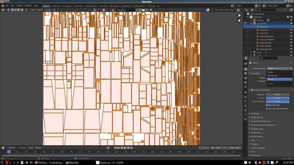
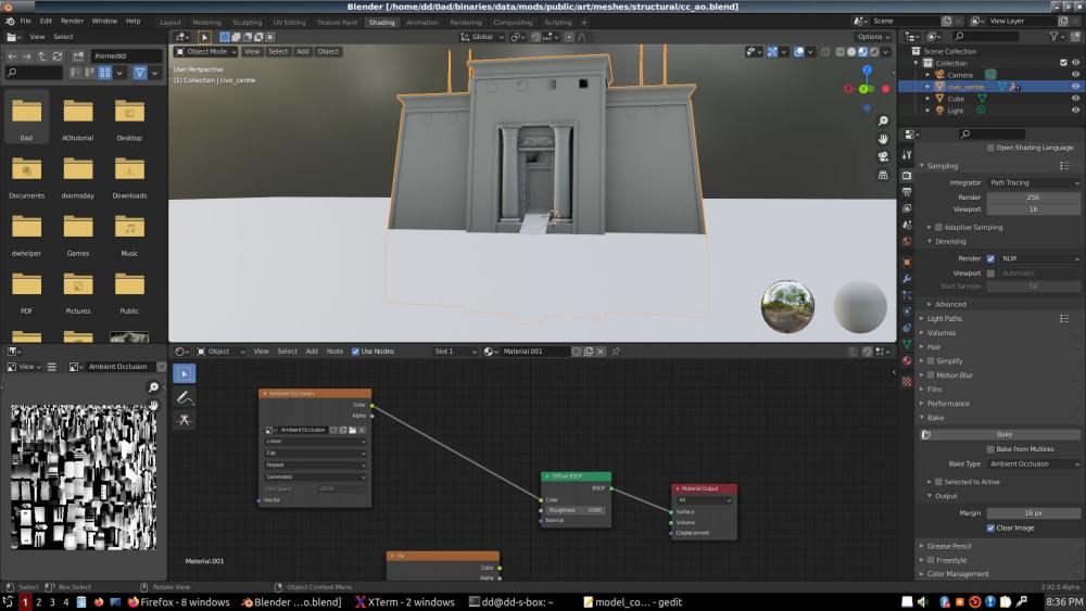
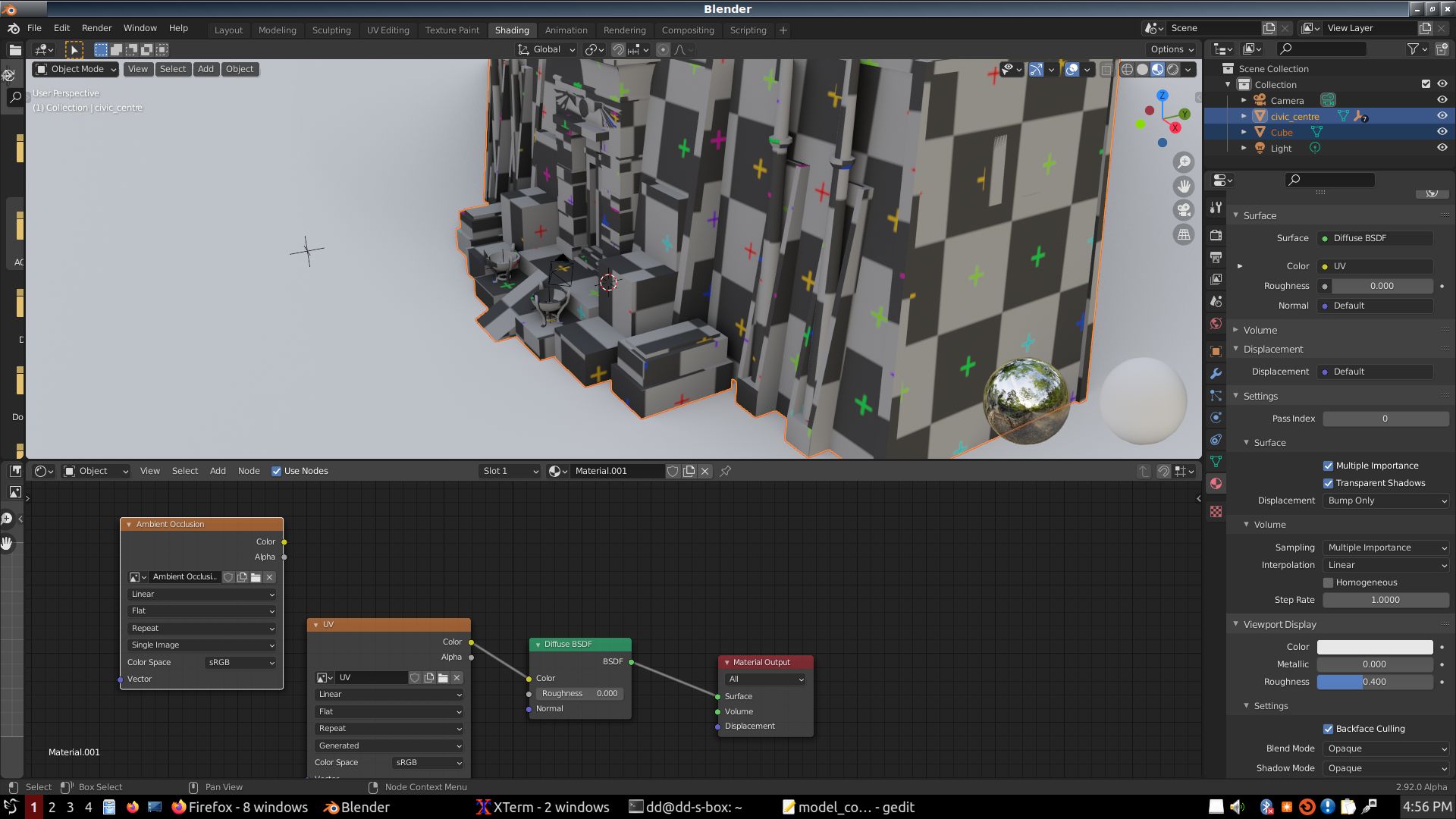
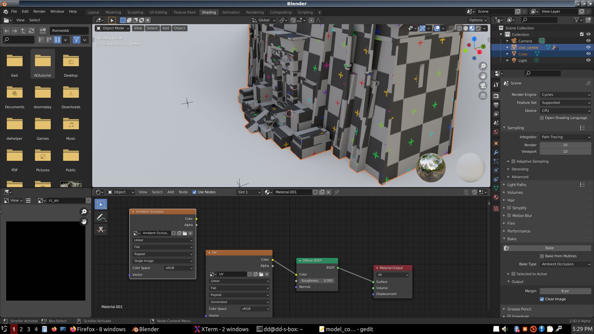
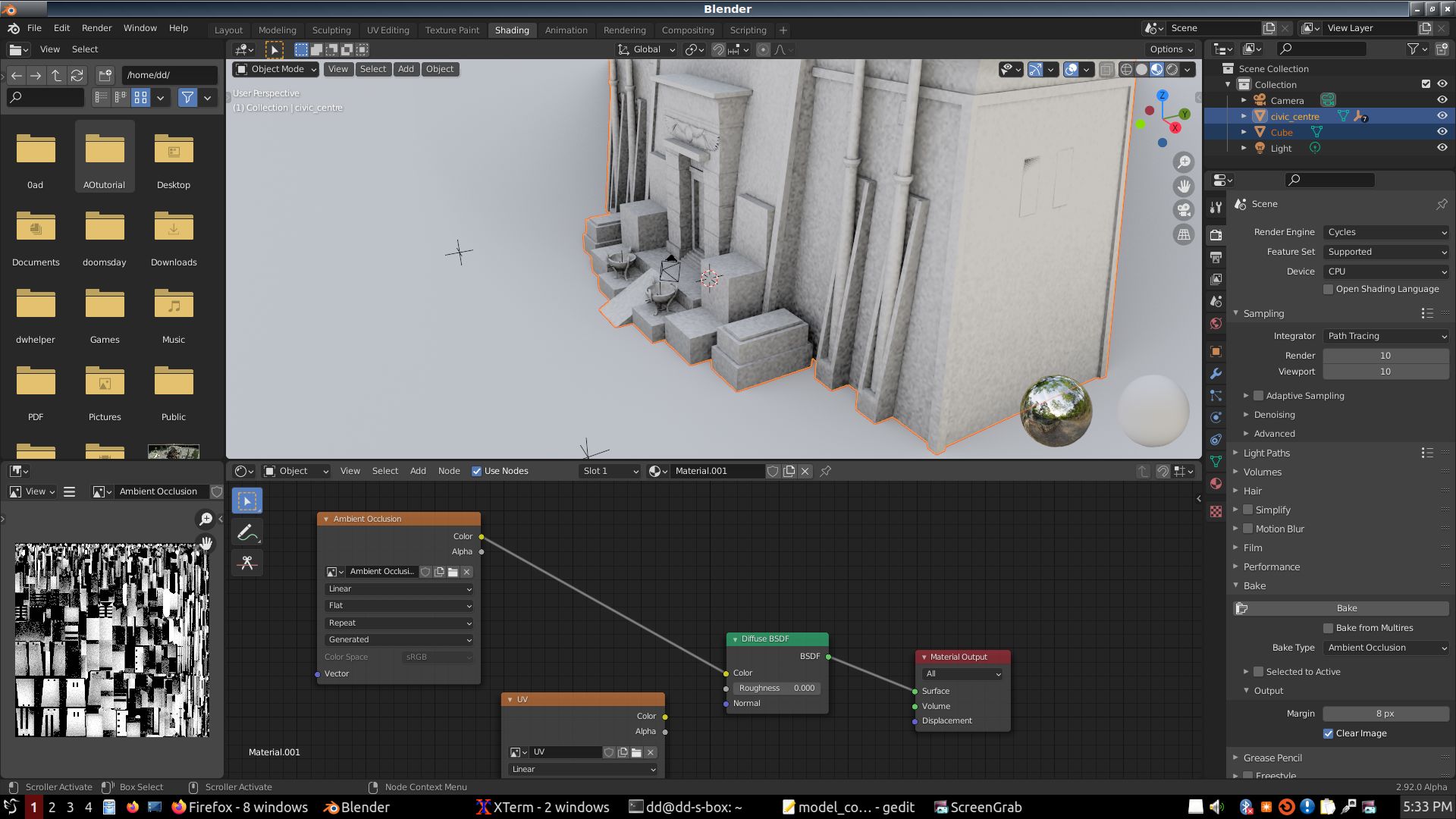
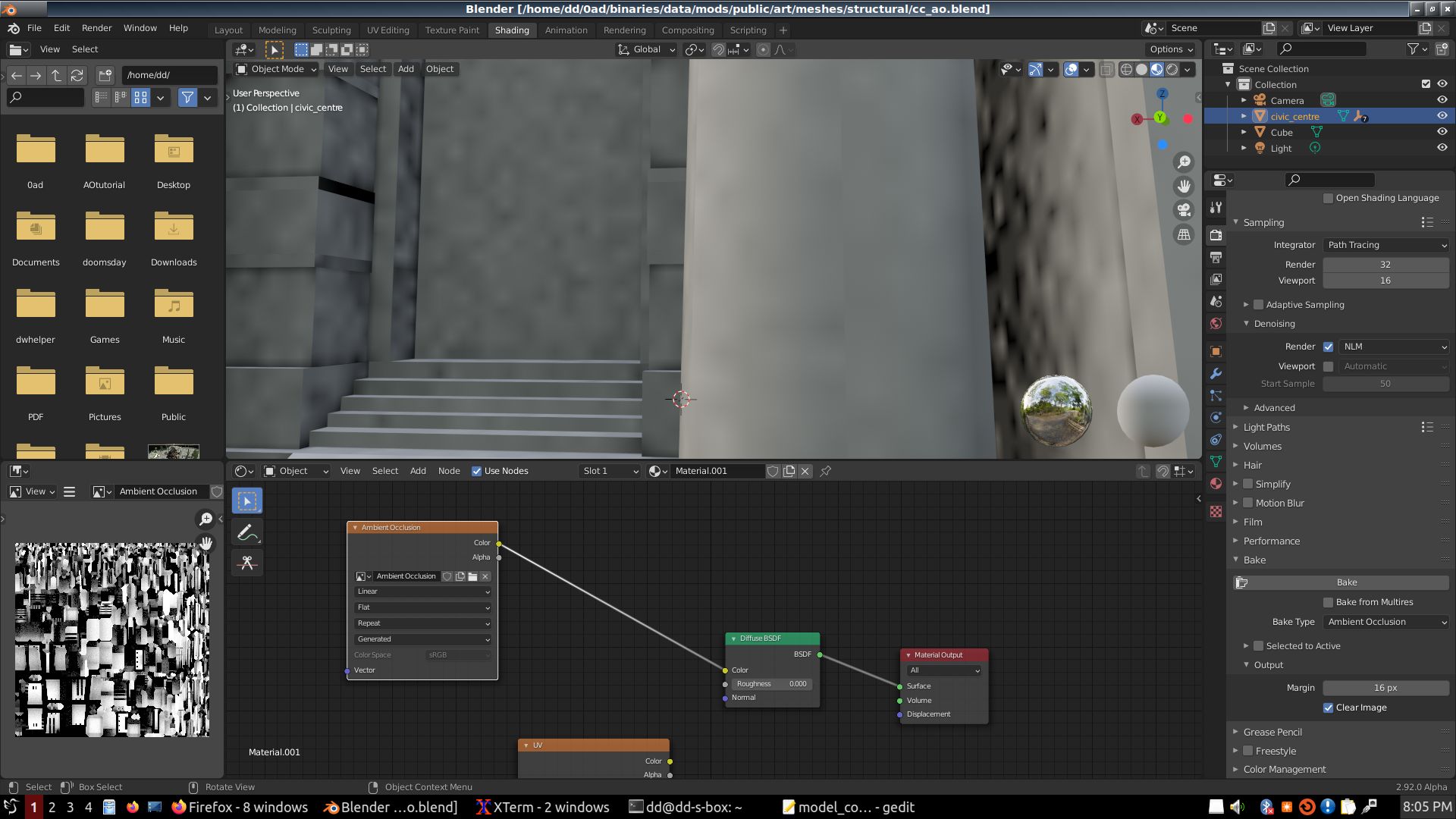
Then come a bunch of screens about setting up Cycles for AO baking, setting up a material, creating a texture, and all that.
Finally, a first AO test, very pixelated due to low setting for samples, since it's just a first test.
Then I increased samples to 256 and baked again.
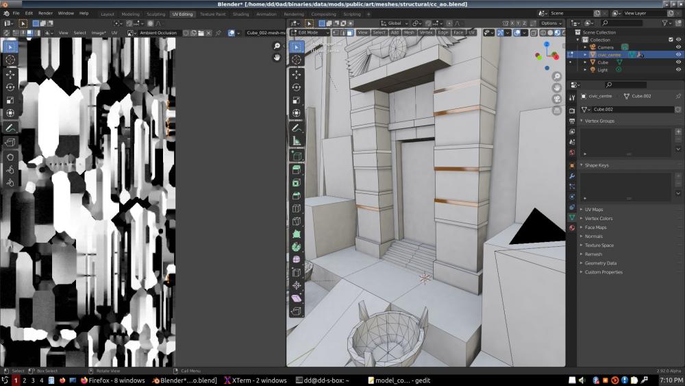
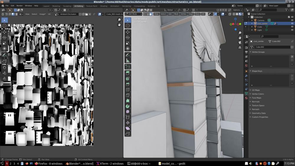
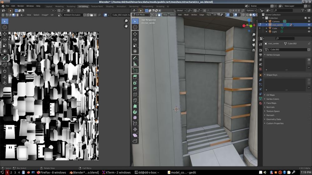
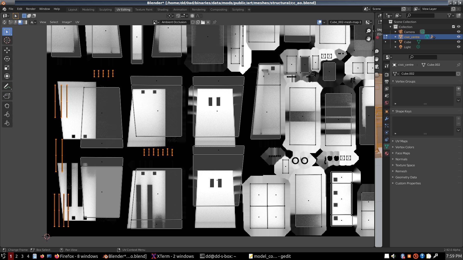
What I wasn't liking at all was the way the UV layout was made, with almost no space at all between islands. That is bad for filtering. When you zoom-out, artifacts may start appearing along polygon edges. Why? Because as you zoom out, the GPU needs to use smaller LOD's of the texture, where each pixel may be 4 pixels of the full size texture, or 16, or 64 ... So if two islands are too close to each other, and one is light, one is dark, as you zoom out, some LOD pixels may be averaging many pixels across two unrelated islands, and end up with a grey edge on each polygon, instead staying light and dark respectively. This is a well known problem, and it is the reason automatic tools for UV layout let you specify how much space you want to leave between islands, and why the AO baking panel has a "Margin" setting, for how many pixels of color extension you want around your islands.
So I selected all the islands, set the scaling and rotation mode to "Individual Centers" and scaled all the islands by 0.75. Then baked my AO again.
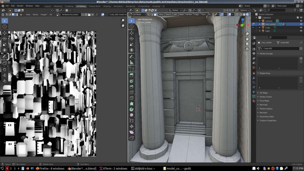
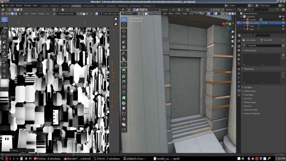
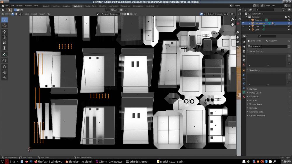
After this I stopped seeing some artifacts, but other artifacts emerged: color bleeding artifacts on a number of wall strips. Thinking that it was due to polygon overlaps in the UV layout, I proceeded to first move all those polygons out of the texture space, then moving some of the big islands near the bottom left corner to make room for them, and I laid them out in their new home.
However, upon baking a new AO, most of the artifacts were gone, but not all. I moved one of the islands for a strip again, and the problem remained.
I think the cause of the artifacts is that those strips are overlapping large polygons. Fixing that would be a complete redesign.
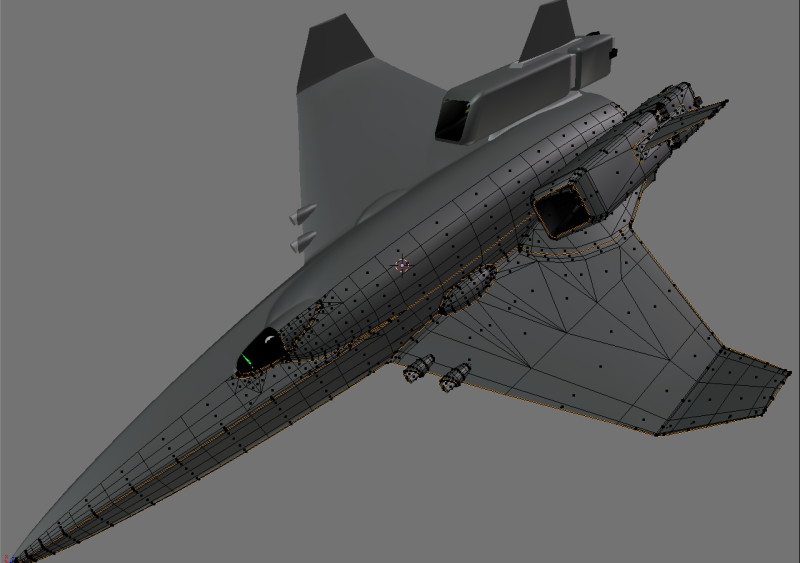
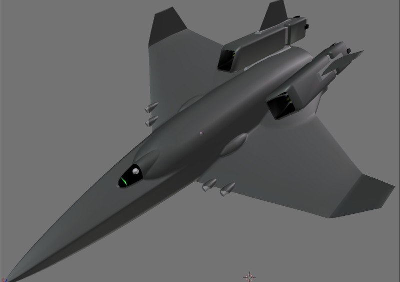
I used to design pretty complex spaceships that were for the most part a single, manifold mesh. (Example pics attached. Note that the only interpenetrating objects are the two little gunmounts on the wing; the rest is a single, continuous mesh.) I never used interpenetrating objects, much less overlapping polygons. To design a building like this in a single manifold, you basically start with a cube, and you subdivide it with CTRL-R (loop cut), Extrude, scale... Just those 3 operations you can follow to turn a cube into an object of just about any complexity. It should not be necessary to have gazillions of interpenetrating cubes and overlapping polygons.
It is not only unnecessary and artifact-dangerous; it is also wasteful of the most precious GPU resource, pixel render operations. The inside of a building like this should be completely empty; it should look just like the outside, but in negative. There should not be gazillions of polygons crisscrossing within the invisible interior. They may be hidden from your eye on the screen, but the GPU tries to paint all those polygons, and ends up aborting each pixel draw after confirming that something is already drawn in the pixel with a lesser Z (closer to the camera). This is the worst thing you can do for graphics performance.
But this is a tutorial for another day.
Another thing that is missing from this tutorial is the obelisks, the lions, and Mr Faro and his wife. I don't know where they are. The AO can't be complete until they grace our building with their beautiful shadows.
Cheers!
-
1
-
-
Stan asked me to write a tutorial on AO baking, due obviously to my criticisms about the way it is done at present.
However, the challenge for me was getting to do this in Blender 2.9, being stuck, as I've been, at 2.7x, unable to handle the frustrations with the new interface, and having to deal with Cycles and all that.
But with the help of people and video tutorials I managed, sort of. There's probably things not needed, or better ways of doing stuff.
Anyways, let's begin:
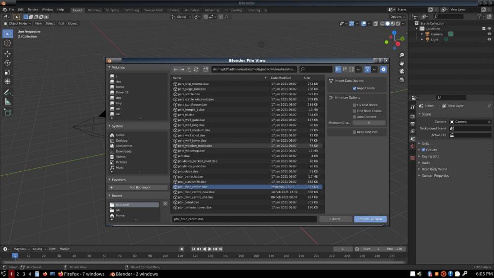
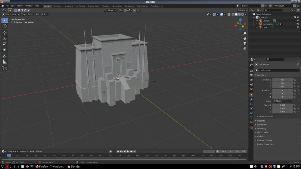
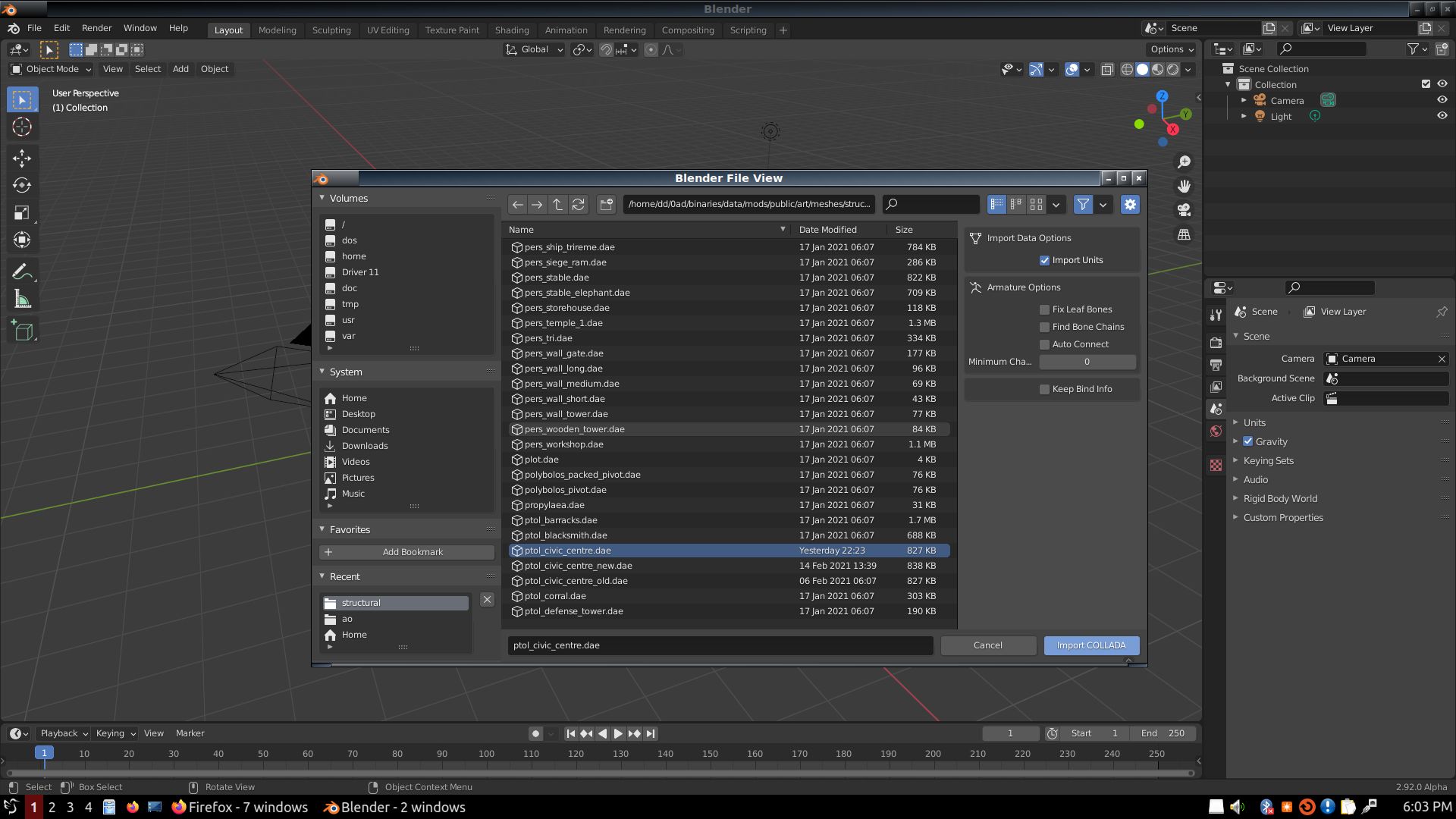
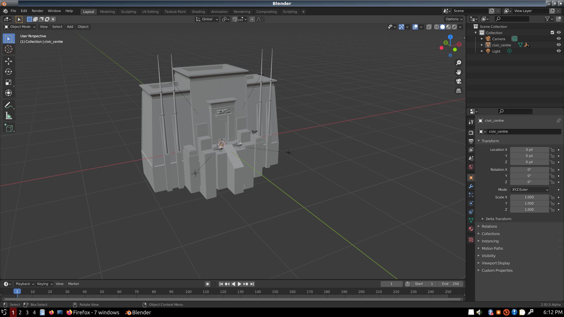
I used the ptol_civic_centre.dae model for the test, since it is a model I became familiar with for different reasons.
So first step is I import it into Blender, WITH units (yards... why not furlongs?).
Sorry; this interface doesn't allow me to intersperse text and images; does it? No way to edit caption, nothing.
Alright, I'll just attach all the images and figure out later how we can turn this into a tutorial.


-
1
-
 1
1
-
-
While my first AO in Blender 2.9 is baking, I finally get the time to read on this.
I absolutely love this post by an Unreal engine developer answering questions in that thread you linked me:
QuoteThe material model is based off of Disney's. I've had experience in the past with a physically based model that was DiffuseColor, SpecularColor, and Gloss. There is nothing more or less physical about it. It is just a different interface to the artist. In my experience there are things about it that are problematic that I intended to solve.
Gloss to some people isn't obvious in how it works. What does gloss mean? Although high gloss and low gloss are perfectly clear to me on more than one occasion there has been confusion or debate about which produces sharper or blurrier reflections. Roughness is clear to everyone. It is immediately understandable and clear as to what effect it has on light. The unfortunate thing is that it is opposite the intuitive intensity of specular reflectance. This means that roughness maps look inverted visually. For this reason some engines have gone with "smoothness" instead, which if I were to do it again I would strongly consider.
DiffuseColor and SpecularColor have a complex relationship that requires a great deal of artist training and is very error prone. Artists need to be taught that metals have black diffuse and colored specular, nonmetals have noncolored specular of about 4%. What is that in sRGB space? These sound simple but trust me, making sure the textures followed rules like this is a long and difficult process. Having the parameter Metallic is much simpler. Is this metallic, yes, no? Now there is nothing to learn or screw up except setting metallic to something not 0 or 1. The learning process with this material model I have seen go much better.
An additional advantage is storage savings. Materials can often assume constants and not require textures for Metallic or Specular. The GBuffer gains one channel by storing Metallic and Specular instead of SpecularColor.
There is a downside being that it disallows some nonphysical materials with diffuse and colored specular. Occasionally that can cause issues but most of the time this is a good thing.
There are many others going the metallic route, Frostbite and The Order come to mind. The Disney presentation made a really big splash.So, there is NO difference between specular/gloss and metal/roughness; it is a nomenclature. Pure semantics. Specular and Metal are the same thing. Gloss is the same as roughness, though they sound like opposites, namely specular power.
Anyways, I'm starting to really like the idea of having a single "color" texture, where a "metal" channel causes the color to go from diffuse to specular. Not only does it not permit incorrect materials at 0 and 1 for "metal"; it even makes sense for intermediate values. Namely, a perfect metallic surface would indeed be black in specular, but as you introduce the types of imperfections that may cause photons to bounce more than once to reflect back out, you are introducing a small measure of diffuse color, which has a higher saturation than the specular color, which the shader can calculate. So, 0.9 for "metal" would give you a less than perfect metallic surface. At the opposite end, diffuse materials are usually colored by metallic content; most dielectrics are colorless; and while most of the light may take multiple bounces to come out, not all of it does, and in fact telescope makers have been looking for a true diffuse material to paint the inside of telescopes with, and it doesn't exist. I can model that on the shader too; it is not therefore ludicrous to have 0.1 for "metal". And if we treat this as a continuum, then we don't need to worry silly about filtering artifacts with our metal channel.
And we save a whopping 3 channels!!!
EDIT: In fact, I think I'm starting to see an even more interesting use of the metal channel. At the middle values, like from .3 to .7, it could represent various types of rocks. The materials used for "stone" and "metal" could come from the .333 and .667 set points of the "metal" channel, in fact...
-
22 hours ago, hyperion said:
ERROR: Failed to compile shader 'shaders/glsl/model_common.vs':
0:138(2): error: `v_half' undeclared
0:138(21): error: `sunVec' undeclared
0:138(21): error: operands to arithmetic operators must be numeric
0:138(11): error: no matching function for call to `normalize(error)'; candidates are:
0:138(11): error: float normalize(float)
0:138(11): error: vec2 normalize(vec2)
0:138(11): error: vec3 normalize(vec3)
1 hour ago, hyperion said:Still get the same error.
I can't imagine how this is possible. Can you verify your model_common.vs is the same as what I have?
Lines 28 to 38 should read,
varying vec4 v_normal;
varying vec3 v_eyeVec;
varying vec3 v_half;
#if USE_SPECULAR || USE_NORMAL_MAP || USE_SPECULAR_MAP || USE_PARALLAX
  #if (USE_INSTANCING || USE_GPU_SKINNING) && (USE_NORMAL_MAP || USE_PARALLAX)
    varying vec4 v_tangent;
    //varying vec3 v_bitangent;
  #endif
#endif
Which declares varying v_half outside of any conditionals.
Then, lines 130 to 138 should read,
  gl_Position = transform * position;

  vec3 eyeVec = cameraPos.xyz - position.xyz;
  vec3 sunVec = -sunDir;
  v_normal.xyz = normal;
  v_eyeVec = eyeVec;
  v_half = normalize(normalize(sunVec) + normalize(eyeVec));
where sunVec is declared as a type vec3 variable, outside of any conditions.
If what you got is the same, I completely don't understand. If it isn't the same, we need to find out why; there should not be such a bug in svn or diff to cause a changed file to be missed...
EDIT: Diff 16014 under D3555 looks right.
@Stan` Thanks, I'm taking a short break from the blender adventure; will get back to it shortly. (To think I used to live my whole life inside Blender, many years ago, but today need to take frustration breaks from it, breaks my heart.)
-
3 hours ago, Stan` said:
Dan could you provide basic steps for correct AO baking in blender 2.9?
2.9 is driving me nuts, as always. I don't understand ANYTHING with this new interface.
I struggled to get set up with the model, the second UV layout, got a blank image loaded, setup evee for AO baking (I could not find AO interfaces for the other engines), I got the output screen set up for PNG RGB 8 bit no compression.
Now, where is the goddam button to bake?
EDIT: Found a tutorial on how to bake AO's in Blender. As is the case with all Blender tutorials, it goes too fast to follow. One thing is clear, though, it uses cycles. I found the cycles interface; tried to bake but it tells me there's "no active texture", whatever active texture is supposed to mean. I think it may be the fact that I don't have a node network set up yet. The guy in the video sets it up so fast it is a blur...
-
Okay, @hyperion fingers and toes crossed... knocking on wood... this should fix the problem.
https://code.wildfiregames.com/D3555
prohibited_shader.patch model_common.fs model_common.vs terrain_common.fs
-
Yes; let me study it first; I'm a 2.79 guy, but I have 2.9; I'll take a look.
-
-
1 hour ago, hyperion said:
If you want ao to always range from 0-1 as mentioned in TODO 1 for any given map you might want to provide a script around imagemagick so you and other users can convert their assets to test this case as well. No need for the shader to take care of it.
True, but there's an issue of quantization if you take an 8-bit deep texture, scale value up by 1.618, and then re-quantize it to 8-bits. If you do that you will get quite noticeable banding artifacts in most assets.
The other two options are a) for the shader to do it, where there's scaling up but no further quantization...
or... b) to re-bake the AO. If you bake AO's from Blender, there is a button you can check for Normalized output. Re-baking would also give us a chance to correct errors with current bakings, besides the lack of normalization, namely that sometimes buildings contain assets like obelisks that in'game deploy outwards, but themselves lack AO. There's also a need to place props under the assets, just for the bakings, to avoid light hitting the model from below ground. Last but not least, it would be good to switch to a baking tool that supports ray dot normal modulation; they look much more natural and realistic.
Of the three choices, I'd favor re-baking, really; but the shader doing it would be second-best. To try to fix the textures would be my last choice by a long shot.
I'll fix the problem with the vertex shader and re-post. Thanks. I wonder why it doesn't report a problem on my machine...
-
26 minutes ago, hyperion said:
AO baking is also a hack
How? And which one? There are two types of AO bakinkg: a) were all rays are counted equally, and b) where rays are multiplied by ray dot normal before accumulating. I think both are pretty scientific. The first represents exact unoccluded visibility. The second represents diffusely reflected omnidirectional light. The fist is good for things like probabilistic occlusion hacks. The second looks the most real when applied to models. Do you mean it's a hack because of the finite samples? Or because it does not take all of the environment into account? Or because it isn't dynamic?
I mean, you could say all of graphics is a hack, since photons move from light sources to eyes, but in graphics we project from the eye, back to light sources...
26 minutes ago, hyperion said:If you hold a leaf towards the sun some light leaks trough, so "transparency" isn't just about glass.
Ah, but that's not "transparency"; it's "translucency". But I get what you mean. If I grab a piece of tinted glass in front of my face and DON'T change the angle, I get constant transparency rate, and therefore something similar to Alpha. But in any case, what I meant is that Alpha is useless in 3D graphics unless you want to model a teleporter.
26 minutes ago, hyperion said:AO map seems gone in your list.
No, it is just the fact that it's in a second UV channel. I'm considering only textures pertaining to material representation, for now.
26 minutes ago, hyperion said:A player_colour bit. If I'm not mistaken alpha is currently used for this.
Isn't player color something the CPU holds? Oh, I know what you mean, a channel for where to show it, right?
26 minutes ago, hyperion said:You mention glass I mentioned a leaf, there are fantasy mods and you talked about a space mod. So the specification for the stack should handle this sort of materials, whether to implement them now, later or never is not that relevant.
Touche. I'll make sure my glass shader will be able to do glass, leaves, plasma, fire and Alpha things.
26 minutes ago, hyperion said:Materials that emit light, lava for instance or fluorescent paint/engine on a spaceship.
Sure, the emissive texture was my favorite texture work in my Vegastrike days. The real value of it is not just glowing things that can be produced without a texture, but self-illumination. Having parts of a ship receive light from other parts of ship, that adds a TON of realism.
26 minutes ago, hyperion said:Clear coating?
That's covered already. Index of refraction, purity of surface and spec power all maxed out will give you the glossiest clear coating in the galaxy.
I don't understand the part of
26 minutes ago, hyperion said:One is specular/gloss, the other metal/roughness.
To me all of that is necessary to describe a material; I don't see where there is a "choice" to make.
-
I almost missed it, myself. Sounding the heads up, so we all watch it live.
By the way, the UAE sent a probe to orbit Mars, and it arrived safely a week ago or so, but since it's the UAE that did it, it gets no media attention.
It is, however, not just a "we did it" thing; it is full of valuable instruments.
-
3
-
-
The texture stack analysis begins...
As I said to hyperion before, I analyze needs first, then look for how to fulfill them. Therefore, starting this analysis from looking at what Blender has to offer is anathema to my need to establish what we're looking for in the first place. Not that I will not look at what Blender, or any parties, have to offer; and not that I'm unwilling to compromise somewhat for the sake of pre-packaged convenience; but, to me, looking at what is available without analyzing what's needed first is a no-no.
Let's start with the boring stuff: we have diffuse.rgb and specular.rgb. These two trinities MUST be mapped to rgb channels of textures in standard manner. Why? Because the parties that have come up with various compression and representation algorithms and formats know what they are doing; they have taken a good look at what is more or less important to color perception; so say a DDS texture typically has different numbers of bits assigned to the three channels for a reason. We certainly would not want to swap the green and blue channels and send red to the alpha channel, or any such horror.
What I am unpleasantly and permanently surprised by is the lack of a texture format (unless I've missed it) where a texture is saved from high precision (float) RGB to compressed RGB normalized (scaled up in brightness) to make the most efficient use of available bits of precision, but packed together with the scaling factor needed by the shader to put it back down to the intended brightness. Maybe it is already done this way and I'm not aware of it? If not, shame on them!
It is clear to me that despite so many years of gaming technology evolution, progress is as slow as molasses. Age of Dragons, I was just reading, use their own format for normalmaps, namely a dds file where the Z component is removed (recomputed on the fly), the U goes to the alpha channel, and V goes to all 3 RGB channels. Curiously, I had come up with that very idea, that exact same solution, 20 years ago, namely to try to get more bits of precision from DDS. What we decided back then, after looking at such options, was to give up on compression for normal maps; we ended up using a PNG. RGB for standard normalmap encoding, and alpha channel for height, if required. So, our texture pack was all compressed EXCEPT for normalmaps; and perhaps we could go that way too, or adopt Age of Dragons' solution, though the latter doesn't give you as much compression as you'd think, considering it only packs two channels, instead of up to four for the PNG solution. And you KNOW you can trust a PNG in terms of quality.
In brief summary of non-metal requirements: We need Index of refraction and surface purity. Index of refraction is an optical quality that determines how much light bounces off a clear material surface (reflects), and how much of it enters (refracts), depending on the angle of incidence; and how much the angle changes when light refracts into the material. In typical rendering of paints and other "two layer" materials, you compute how much light reflects first; becomes your non-metallic specular; then you compute what happens to the rest of the light, the light refracting. It presumably meets a colored particle, becomes colored by the diffuse color of the layer underneath, then attempts to come out of the transparent medium again... BUT MAY bounce back in, be colored again, and make another run for it. A good shader models all this. Anyways, the Surface Purity would be 1.0 for high quality car paints, and as low as 0.5 for the dullest plastic. It tells the shader what percentage of the surface of the material is purely clear, glossy material, versus exposing pigment particles. In a plastic, pigments and the clear medium are not layered but rather mixed.
ATTENTION ARTISTS, good stuff for you below...
Another channel needed is the specular power channel, which is shared by metallic and non-metallic rendering, as it describes the roughness of a reflecting surface regardless of whether it is reflecting metallically or dielectrically. The name "specular power" might throw you off... It has nothing to do with horses, Watts, politics, or even light intensities; it simply refers to the core math formula used in Phong shading: cos(angle)^(sp), coded as pow( dot(half_vec,normal), specPower ).... dot(x,y) is a multiplication of two vectors ("dot product"), term by term across, with the results added up, which in the case of unit-vectors represents the cosine of the angle between them; normal is the normal to the surface (for the current pixel, actually interpolated by the vertex shader from nearby vertex normals); half_vec is the median between the incident light vector and the view vector... So, if the half-vector aligns well with the surface normal it means we have a well aligned reflection and the cosine of the angle is very close to one, which when raised to the 42nd power (multiplied by itself 42 times), or whatever the specular power of the material is, will still be close to one, and give you a bright reflection. With a low specular power (a very rough surface), you can play with the angle quite a bit and still see light reflected. If the surface is highly polished (high specular power), even a small deviation of the angle will cause the reflection intensity to drop, due to the high exponent (sharper reflections). Note however that the Phong shading algorithm has no basis in physics or optics. It's just a hack that looks good. For non-programmers, you may still be scratching your head about WHEN is all this math happening... It may surprise you to know it is done per-pixel. In fact, in my last shader, I have enough code to fill several pages of math, with several uses of the pow(x,y) function, and it is all done per-pixel rendered, per render-frame. The way modern GPU's meet the challenge is by having many complete shader units (a thousand of them is not unheard of) working in parallel, each assigned to one pixel at a time. if there are 3 million pixels on your screen, it can be covered by 1000 shader engines processing 3,000 pixels each.
... specially this:
But back to the specular power channel and why it is so important. As I've mentioned elsewhere, the simplest way to represent a metal is with some color in specular and black in diffuse. However, you do that and it doesn't look like metal at all, and you wonder what's going on. Heck, you might even resort to taking photos of stainless steel sheets, and throwing them into the game, and it would only look good when looking at the metal statically; the moment you move, you realize it is a photograph. The look of metal is a dynamic behavior; not a static one. Walk by a sheet of stainless steel, looking at the blurry reflections off it as you walk slowly by it. What do you see? You see lots of variations in the reflectivity pattern; but NOT in the intensity. The intensity of reflectivity, the specular color of the metal, doesn't change much at all as you walk. What does change, then? What changes is small, subtle variations of surface roughness. And this is how you can represent EXACTLY that: Add even a very subtle, ultra low gain random scatter noise to the (50% gray, say) specular power of your model of stainless steel; now, as you walk by it in-game you will see those very subtle light shimmers you see when you walk by a sheet of stainless steel. In fact, it will look exactly like a sheet of stainless steel. You will see it in how reflected lights play on it. THAT IS THE POWER OF SPECULAR POWER !!!
For another example, say you have a wooden table in a room that you have painstakingly modeled and texture, but it doesn't look photorealistic no matter... Well, take the texture you use to depict the wood grain, dim it, and throw it into the specular power channel. Now, when you are looking at a light reflecting off the table, the brighter areas in the specpower texture will also look brighter on reflection, but the image of the light will be smaller for them; while the darker zones of the wood fiber pattern in specpower will give a dimmer but wider image of the light. The overall effect is a crawling reflection that strongly brings out the fibers along the edges of light reflections, but not elsewhere, making the fibers look far more real than if you tried to slap a 4k by 4k normalmap on them, while using a single channel!
For another example, say you have the same table, and you want to show a round mark from a glass or mug that once sat on that table. You draw a circle, fudge it, whatever; but where do you put it? In the diffuse texture it will look like a paint mark. In the specular texture it will look like either a silver deposition mark or like black ink. No matter what you do it looks "too much"... Well, try throwing it in the specpower channel... If your circle makes the channel brighter, it will look like a circle of water or oil on the table. If it makes the channel darker it will look like a sugar mark. Either way, you won't even see the mark on the table unless and until you see variations in the reflectivity of a light source, as you walk around the table, which is as it should be. THAT IS THE POWER OF SPECULAR POWER !!!
So, having discussed its use, let me say that the packing of this channel in the texture pack is rather critical. Specular power can range from as low as 1.0 for an intentionally shimmery material, think Hollywood star dresses, to about a million to honestly represent the polish of a mirror. The minimum needed is 8 bits of precision. The good news is that it's not absolute precision critical; more a matter of ability to locally represent subtle variations. I'm not looking into ranges, linearities and representations for the texture channels yet, but I will just mention that the standard way to pack specular power leaves MUCH to be desired. Mapping specular powers from 1.0 to 256.0 as 0-255 char integers has been done, but it's not very useful. The difference between 6th and 7th power is HUGE. The difference between 249th and 250th power is unnoticeable. Furthermore, a difference between 1000th power and 1050th power is noticeable and useful, but a system limited to 256.0 power can't even represent it. As I've suggested elsewhere, I think a 1.0/sqrt(sqrt(specpower)) would work much better. But we'll discuss such subtleties later.
Other channels needed:
Alpha? Let me say something about alpha: Alpha blending is for the birds. Nothing in the real world has "alpha". You don't go to a hardware store or a glass shop and ask for "alpha of 0.7 material, please!" Glass has transparency that changes with view angle by Fresnel law. Only in fiction there's alpha, such as when people are teleporting, and not only does it not happen in real life, but in fact could never happen. For transparency, a "glass shader" (transparent materials shader) is what's needed. Furthermore, the right draw order for transparent materials and objects is from back to front, wheras the more efficient draw order for solid (opaque) materials is front to back; so you don't want to mix opaque and transparent in the same material object. If you have a house with glass windows, the windows should be separated from the house at render time, and segregated to transparent and opaque rendering stages respectively. All that to say I'm not a big fan of having an alpha channel, at all. However, there's something similar to alpha blending that involves no blending, called "alpha testing", typically uses a single bit alpha, and can be used during opaque rendering from front to back, as areas with alpha zero are not written to the buffer at all, no Z, nothing. This is perfect for making textures for plant leaf bunches, for example. And so I AM a big fan of having a one-bit alpha channel somewhere for use as a hole-maker; and I don't want to jump the gun here, but just to remind myself of the thought, it should be packed together with the diffuse RGB in the traditional way, rather that be thrown onto another texture, as there is plenty support in real time as well as off-line tools for standard RGBA bundling.
There is another alpha channel presently being used, I think in the specular texture, that governs "self-lighting", which is a misleading term; it actually means a reflective to emissive control channel. I don't know what it is used for, but probably needs to stay there.
Another "single bit alpha channel" candidate that's been discussed and pretty much agreed on is "metal/non-metal". I've no idea where it could go. Having this single bit channel helps save a ton of texture space by allowing us to re-use the specular texture for dielectric constant and purity. There is a third channel left over, however. Perhaps good for thickness.
One thing we will NOT be able to do with this packing, using the metal/non-metal channel, is representing passivated oxide metals. Think of a modded Harley Davidson, with LOTS of chrome. If the exhaust pipe out of the cylinders, leading to the muffler/tail-pipe, is itself heavily chrome-plated, you will see something very peculiar happen to it. In areas close to the cylinder, the pipe will shine with rainbow color tinted reflections as you move around it. The reason for this is that the heat of the cylinder causes chrome to oxidize further and faster than cool chrome parts, forming a thicker layer of chromium oxide, which is a composite material with non-metal characteristics: transparent, having a dielectric constant. The angle at which light refracts into the oxide layer varies with angle AND with wavelength; so each color channel will follow different paths within the dielectric layer, and sometimes come back in phase, sometimes out of phase. I modeled this in a shader 20 years ago. Unfortunately, the diffuse texture plus dielectric layer model is good for paints, plastics, and many things; but modelling thick passivating rust requires specular plus dielectric. It would have been good for sun glints off swords giving rainbow tinted lense-flares...
EDIT: There is another way we might actually be able to pull off the above trick, and that is, if instead of using the metal/non-metal channel to switch between using the second texture for specular or non-metallic channels, we use it to interpret the first texture as diffuse or as specular. The reason this is possible is that non-metals don't have a "specular color", and metals don't really have s diffuse color either... And you might ask, okay, how do I put rust on steel, then? Well, rust is a non-metal, optically... Now, alpha-blending rust on steel may be a bit of a problem with this scheme, though... But anyways, if we were to do this, we'd have our index of refraction channel regardless of whether the bottom layer is diffuse or metallic. This would allow us to show metals like chromium and aluminium, which rust transparently, it would allow us to have rainbow reflecting steels, and would even allow us to have a rust-proof lacker layer applied on top of bronze or copper. And actually, it is not entirely inconceivable, in that case, for the metal/non-metal channel to have a value between 0 and 1, thus effectively mixing two paradigms ... food for thought! ... in which case it could be thrown in the blue channel of the 2nd texture. For artists, this could boil down to a choice between simple representation of a diffuse color material, or a specular metal, or to represent both, and have a mix mask. Thus, you could represent red iron oxide by itself, diffuse, spec power, index of refraction, whatever; and another set of textures representing the clean metal, then provide a gray-scale texture with blotches of blackness and grey representing rust, over a white background representing clean metal, press a button and voila!, the resulting first texture alternates between rust diffuse and grey specular color, and the blue channel in the second texture is telling the shader "this red color is rust", and "that gray color is metal". It could look photo-realistic while using a minimum of channels to represent.
I have to go, so I'll post this partial analysis for now and continue later. One other channel that immediately comes to mind is detail texture modulation.
I think we are over the limit of what we can pack in 3 textures, already; I have a strong feeling this is going to be a 4 texture packing. That's "packing", though; at the artistic level there could be a dozen. Other texture channes for consideration are the RGB for a damage texture, to alpha-blend as a unit takes hits... blood dripping, etc.
-
1
-
-
I've kept revisiting and reuploading the patch to D3555. Nothing too important. I had leftover code for my attempt at using the skybox as environment map. Spaces, indentations, dotting comments...
And I made one minor optimization that saved one call to sqrt().
Anyhow, if you want to have the latest, here it is, linked and attached.
https://code.wildfiregames.com/D3555
prohibited_shader.patch model_common.fs model_common.vs terrain_common.fs
-
Stan left some comments for me at the D3555 patch, mostly style things to fix, comments, blank space.
The one change I wasn't able to make is diffing from the root folder; when I do the diff includes gazillions of C++ files I was working on in the sources folder coming to 4MB and change, which the Phabricator rejects. There must be a way to avoid that, but I'm no svn expert.
For whatever's worth, here's the updated patch, diffd again from /binaries, but cleaned up and with the civic center removed; wasn't important. And I include the shaders too, for good measure.
EDIT, re-uploading; fixed everything, diffed from root folder. Updated D3555 patch again.
prohibited_shader.patch terrain_common.fs model_common.fs model_common.vs


Next Shader Development
in Applications and Contributions
Posted · Edited by DanW58
Okay, it's not that easy. I just went to refresh my memory on DXT texture formats, and the 5,5,5,1 format doesn't exist.
The way it is, which is now coming back, after so many years, is that DDS takes 16 texels at a time (and they call each 16-texel bunch ... a "texel" again... boggles the mind... the world is just drowning in stupidity), places the four incoming colors in a 3D color space, and tries to find the nearest line to all four points; then finds the closest point on the line from each of the points. For the two outer points, it encodes the color as 5,6,5 bits for rgb, and for the two inner points it interpolates using a two bit number. So, 16 bits for each end-color is 32 bits, plus a 2-bit index for each of the 16 texels = 32 bits. 32+32 = 64 bits per 16-texel "texel", which works out to 4 bits per texel (versus 24 bits for uncompressed sRGB). Of course, only 4 colors are actually present in each group of 16 texels, which is rather apathetic. Works well if the image is filtered and dull; but produces a lot of artifacts with sharp images. Well, not necessarily; the issue is with color channel correlations or the lack thereof. The great advantage of this format is that it decompresses locally. If you are decompressing jpg, for example, you have to decompress the entire image at once, so when using jpg or png formats the videocard driver has to do the decompression, and the image is put in video memory uncompressed. DDS format decompresses locally, so the whole texture can be loaded into graphics memory compressed, and decompressed on the fly by the gpu as it reads it, taking a lot less space in video memory (1/4 as much space, to be exact).
The take-away is that in an image, depending on the detail and sharpness, you can have uncorrelated R, G and B data scatter, but DXT compression assumes it can bundle this scatter into a single straight line between two colors to interpolate across. In other words, it depends on R/G/B correlation. If you have a linear gradient, whether vertical, horizontal, or at any angle, DXT will capture that very well. But for UNcorrelated change it can be terrible. So, for blurry images it may work well ...
What I just described above is actually the most basic rgb format of dxt, namely DXT1, though. There's also two formats containing alpha channels: DXT3 and DXT5. DXT3 and DXT5 both result in the same size texture from a given RGBA input. They just express alpha two different ways, better suited to different circumstances:
In DXT5, the minimum and maximum alpha values in the 16-texel "texel" are expressed as 8-bit numbers; so that's 16 bits. Then the 16 texels are interpolated between those two extremes via 3-bit indexes, resulting in up to 8 shades of alpha per 16-texel group. 3 bits x 16 texels = 48 bits. 16+48 = 64, so the size of a DXT5 is double the size of a DXT1, but the quality of the alpha channel is much higher than for rgb, though it may suffer a bit in the interpolation.
In DXT3, each of the 16 texels gets an individual alpha value; no fancy interpolations; but each value is 4-bits only. 16 x 4 = 64.
DXT5 works better for smoothly changing alpha channels, or for packing smoothly changing data, such as AO.
For images with real detail in alpha, such as holes in a fence, you're much better off with DXT3. For data-packing, any smoothly changing data benefitting from higher precision, like AO, would be best encoded as DXT5 alpha, but rapidly changing, detailed data not needing much precision, DXT3's alpha channel is much better.
But there's no such thing as a DXT format with 1-bit alpha for alpha-testing. Actually, there probably is, as DXT has a phone-book of texture formats, but the ones commonly used are DXT1,3,5, and I wonder if there's even hardware support for the others.