vts
-
Posts
110 -
Joined
-
Last visited
-
Days Won
2
Everything posted by vts
-
The second link has an example of a building outline using a square texture; not sure if that's what you're asking? In any case, you can apply any texture, so you can have whatever kind of fancy outline you'd like. In the current implementation all units with square footprints get a square selection texture and the circular ones get a circle, but you can use any texture you want instead. You'd just need a way to specify one, but I imagine that'd be just a matter of adding some XML to the template or something.
-
I believe the hero stars are decals which are part of the model hierarchy, which weren't really designed to have tons of them simultaneously (or so I'm told). These selection overlays are different in that they're separate from the model hierarchy and don't necessarily stick to the terrain like the stars do, are more optimized for mass rendering, and of course are only displayed when you select the unit. But yes, you'd be able to achieve the same effect by using a star texture for the overlay. That's the reason for using textures instead of e.g. reusing the textured overlay lines to make small outlines around units, so you can use all kinds of fancy graphics instead of a standard outline.
-
Alright, so I'm working on the ticket to improve the unit selection rings to make them look prettier and not just a simple 1px aliased line. I'm now at the point where I have a proof of concept implementation working, but there are a few questions that I'd need answered to know in which direction to continue with it. This may involve the art people as well, so I figured I'd bring this discussion here to get as much input as I can. This may get a bit technical, but hey, this is the technical discussion forum after all . So the goal is to have pretty unit selection rings, preferably using textures so that we can extend it later on to also add various fancy graphics and not only basic rectangles and circles. This graphic was cited as an example of what this system would ideally support: Keeping that in mind, the plan was to use textured quads (rectangles in OpenGL-speak). However, there are some issues with using textures: If you apply the same texture to display a selection ring of larger sizes, then the texture will get stretched and a 1px white / 2px player color / 1px white outline might become a 4px / 8px / 4px outline. So, to achieve a consistent visual outline width, you'd ideally have to create a separate texture for each selection outline size. This is what the proof of concept currently does, and it comes down to a total of 126 textures. This is a large amount of textures, and in practice there are another 126 mask textures involved to indicate where the player color should be applied, totalling 252 textures to be loaded in the worst-case scenario. I imagine it's unlikely that you'd ever actually need to load this many textures at the same time to render a scene, but I have no data to see how many unique unit footprint sizes there are on average in a scene. To reduce this amount, a scheme was suggested where you'd use the same texture for footprint sizes that are very close, like circles of radius 0.75 and 1, and accept the (hopefully small) visual difference. The amount of textures that is eliminated depends on how much visual accuracy you're willing to sacrifice. I've yet to try out a full range of accuracies to determine roughly at which point things start becoming unacceptable, but some quick tests suggest a reduction to only maybe 90-ish unique footprints (not counting masks). That's still a lot of textures. The current implementation sorts the rendering by texture so as to reduce swapping, but there are still potentially many textures that need to be loaded to render a scene, and I have no idea how many textures of which sizes the game can typically handle. I'm also unsure how to best manage these in code; I've noticed that ingame there is usually this short black-flicker when the texture is first used, i.e. while it's being loaded. I've noticed that textures can be prefetched which might be useful for this, but again, I have this feeling that prefetching like 50+ textures is not a very good idea. I'd love some input on how to best deal with this. Using this many textures may pose some issues for artists as well. The current implementation uses a python script to read out all possible footprint sizes and shapes from the templates and generate the textures accordingly. This is fine for basic geometric shapes like circles and rectangles, but if we ever want to apply fancy graphics like in the image above to units of various footprint sizes, then the same texture is gonna need to be replicated a bunch of times in various sizes, with the additional constraint that the texture canvas must be a power-of-two in width and height. To at least somewhat accomodate this, I've created a small python script that will resize an image to its next power of two dimensions and fill the excess space with transparent pixels. Naming conventions and resolution is another issue: the engine needs a way to identify which version of a texture matches a particular footprint size from the texture name, and also the exact dimensions of the actual texture within its canvas (ie. what part of the image is transparent filler to reach pow2 dimensions and what part is actual texture). The latter depends on the resolution with which world-space units are mapped to texture pixels, i.e. how many pixels you, the artist, would like to use to achieve a texture that looks decent for that particular footprint size. Currently it defines a resolution of 8px per world-space unit, so that a footprint that is defined in XML as having radius 1.5 will have a 12px radius and 24px diameter in the texture. The convention, then, is to name that texture circle_24x24.png, and the engine would use those dimensions to determine exactly where the actual texture is located within the surrounding canvas (in this case, 32x32). The problem with this is twofold:First of all, it forces a resolution of 8px upon you, and this is hardcoded into the engine and hence unchangeable (and you'd have to redo all textures if you ever change it).Second, you may want to use different resolutions for different footprint sizes, or for various textures. For instance, I've found that 8px is sufficient for large units, but it looks bad for small circles. Or maybe you're working on a fancy graphic like the one above but need a higher resolution to make it look decent. To illustrate, look at the two selection rings below. They're both for a hellene female citizen, which have a circular footprint with a radius of 1.0 world-space units. In the left image the resolution is 8px, in the right one it's 12px: Clearly, the 8px one looks bad, while the 12px one might tentatively be called acceptable. However, for larger units 8px is plenty, and it'd actually be preferable to not use anything higher for them since that may cause jumps to the next pow2 canvas sizes and further increase the texture load -- probably not a good idea if you have on the order of a hundred of them. All in all, I'm not sure how to best handle this in a manner that's friendly to artists (because whatever fancy rules you come up with, the artists and the naming convention will have to consistently apply them). I've seen some textures.xml files around; I don't know if those are intended for this kind of thing, but maybe a texture listing in XML would be a decent solution as those would easily allow you to specify things like the resolution and also allow for location independence of the actual texture files. But of course, the file would need to be kept synchronized. [*]The current implementation tries to be as efficient as possible about rendering the quads, primarily by two means: It allocates a single VBO, and reuses this buffer each frame instead of constantly releasing and re-allocating buffers.As mentioned, it sorts the selection overlays to be rendered by texture, so as to prevent excessive texture swapping. The vertex buffer that is allocated is of maximum size, so as to accomodate as many overlay quads as possible without the need for reallocations. This implies that it supports a maximum of 16K vertices. So the question is: is this enough? I was told on IRC that the maximum amount of units that can be simultaneously selected is capped at about 300, which means that this is probably enough, but it depends on whether the overlay for a single (large) unit can take up multiple quads or not, and if so by the way they are indexed. The reason why multiple quads for a single selection ring may be needed is that they serve to make the outline "stick" to the terrain better if the unit is large and its outline spans several tiles (which may not be at the same elevation). However, supporting multiple quads per overlay introduces substantial additional complexity. It implies that we must use a separate index buffer and also keep track of a lot of technical stuff like offsets and number of indices per overlay in the large, statically-allocated buffer. Actually computing these quad's vertex locations is very much non-trivial as well, since units may be arbitrarily rotated -- and keep in mind that these computations will have to be performed every frame (units can move) for every selectable unit, which quickly adds up. If each overlay were to be only a single quad, then we could get rid of all this extra complexity, and we'd also have a guarantee that the single buffer supports exactly 4K quads and hence 4K selection rings, which is guaranteed to be enough if the hardcoded selection limit is indeed 300. However, this will look bad if the terrain under a large unit or building is somewhat hilly. For instance, if a wide unit is walking through a ravine, then with a single quad the selection ring will disappear into the sides instead of "crawling up" the sides (although I personally would find that to be acceptable given the advantages it brings). Someone on IRC mentioned that the ground beneath buildings may need to be flattened when it gets built, in which case single quads should be no problem at all. Nobody I've asked could actually confirm whether this flattening of the ground under buildings is something that I can rely on though, so I'm hoping someone can confirm or deny this. Whew, I think that's about it. Hope I made the choices that need to be made clear without getting too involved; if not, please let me know and I will try to explain more clearly. For reference, some screenshots of the current implementation (at 8px resolution, so circles may look a bit shoddy):

-
By the way, here's a screenshot of how the dashed lines work across the SoD (haven't had time to post these earlier). Since these screenshots were taken the color of the dashes has changed to red inside the SoD and the brightness is now even across the entire line, but the general idea is still the same: More imagery at http://imgur.com/a/XIEzq
-
KISS is probably indeed the way to go here. The rally point marker lines are entirely non-mission-critical anyway, and the patch is already quite large as it is. Going out of our way to add some fancypants recalculation scheme does not seem to be worth the effort at this point
-
I'm a sucker for movie scores, and also for piano music. Found this gem buried in Insidious, so naturally, I had to find out what it was. http://www.youtube.com/watch?v=GTkzyyv0DuA
-
Well that's kind of the problem. For clarity, the situation I was referring to is when you first place the rally points, and then some time later someone puts a building right along your rally point path. A sort of trigger like you mentioned would be perfect, but unfortunately I don't think there currently is such a thing. Nor do I think having it would necessarily be a good idea, as it all contributes to overhead to which pathfinding is already quite sensitive.
-
Still working on this, just really swamped with work right now. I've been editing the shaders to allow the rally point lines to be rendered inside the SoD and I've also added some generic code to create dashed lines. A few issues remain which I'd like to discuss: 1) In the SoD, the idea was to render a dashed straight line from the edge of the SoD to the rally point itself so that the user doesn't get any information about the terrain or enemy buildings from the path. A problem however is that in the SoD, everything is still rendered, only entirely in black. That means the dashed rally point line can still be obstructed visually by black terrain and buildings at some camera angles. Without entirely rewriting the way the SoD is rendered (which I would not recommend), I suppose the best way would be to add a rendering pass that goes after everything else and which doesn't care about depth testing and whatnot so that it would just get drawn through any terrain inside the SoD or something. 2) Right now the long-range pathfinder is used to build an initial path which is then further post-processed. What should happen if a building gets placed smack in the middle of the rally point line? Do we ignore it or recalculate? I'd also be interested to know how to detect this in code, as I'm not yet very familiar with the internals of the pathfinder.
-

Build Limits / Restrictions
vts replied to historic_bruno's topic in Game Development & Technical Discussion
Right, so I think a disable="" attribute would be appropriate, much like the ones that already in place to disable parent components. I just think "magic" values like 9999 or something should be avoided, especially in a markup language as flexible as XML. By the way, <BuildRestrictions> implies that multiple <XxxRestriction> elements may follow. How would that work with overriding, e.g. if you only want to override a single restriction? Unless there's guaranteed to be only one of each restriction type (which could very well be a possibility), you'd need some kind of ID to be able to override a single one, wouldn't you? And what if there are restrictions that apply to different territories and/or categories? Right now the territory and category apply to all of the restrictions that follow, which might not necessarily be what you want. -
Build Limits / Restrictions
vts replied to historic_bruno's topic in Game Development & Technical Discussion
Why not just leave out the <MaxDistance> node? No max distance, so no element defining one, nice and clean. -
I'm not touching the pathfinder, I'm merely editing the path it produces. Although I agree that it would look goofy to have a visible path that units don't actually follow, this is currently not going to happen anyway because units are spawned at randomly-picked locations around the building. On top of that, unit movement is controlled by the short-range pathfinder, which only uses the long-range path as an incremental guide to compute its own (more detailed) path, so from the get go there's really no guarantee that a long-range path will be representative of actual unit movement.
-
Update; I've added some visibility checks between consequent waypoints, to reduce curviness from the pathfinder. The basic idea is that, as long as two waypoints have a straight visibility line between them, there's no reason to take any path between them other than a straight line. Humans don't walk from point A to point B by taking 10 curves along the way, they walk as straight as possible. Two points are considered to have a visible line between them if the 2D obstruction manager says that there aren't any obstructions between them, and if their terrain height difference is below a particular threshold. This allows for large straight lines on flat terrains, while at the same time keeping the keypoints close enough to get a smooth line on hills and slopes. I also fixed an interpolation issue that caused funky curved endings on either side. Here's an old vs. new comparison: The new image has debug overlays turned on; the red circles are keypoints, the white ones are interpolated points. For starters, you can see that the path is a lot more like the path an actual person might walk. As you can see, the lower keypoint in the S-curve around the rock in the old image was eliminated, producing a more straightforward path along the rock. Also, the line ends in a nice straight ending instead of curving at the last minute. The nice thing about this is that slightly moving the rally point will only change the curvature of the last segment slightly, as you would expect. Here's another image showing how the path is made to be more straightforward instead of sticking to the edges of obstacles: And just for fun, here's an image showing the elimination of consecutive keypoints on flats while maintaining them on slopes: All in all, I think it's an improvement. Thoughts?
-
Jeru - none of this code is committed yet, but I have Fraps so I could record a video of it if you like. Are you sure you want a video of it in its current state though? It's using just temporary testing textures for now, and the path is oftentimes still a bit too curvy too make sense. And if so, would you want a particular setting for the video, like an exit point of barracks during a battle or something or a will a basic one-building demo do? Also, I'd be interested to hear if anyone knows how to get smooth camera paths so the video wouldn't look jaggy.
-
That would be where the pathfinder calls it quits, so that should be easy enough. If there is no path from the building to the rally point (according to the long-range pathfinder at least), then no line will be drawn. The rally point flag may still be there though, so I'm not sure if that's the desired behaviour.
-
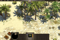
Greetings -- I'm new to the 0 A.D. community, I can do some programming and I have some spare time on my hands, so I figured why not see if I can help out. So for the last week or so, I've been working on getting this ticket fixed: Render marker line between building and rally point. With a lot of help and patience from the kind people on IRC, I've now reached a point where I think it would be useful to get some feedback from everyone to hear your opinions on the contributions I have to make and whether I did it right. So here's how it looks. For testing purposed, I've been using a very simple black and white texture for the path, but any texture/color can be chosen -- this is just a placeholder. Ideally rally point paths should be visually unobtrusive, but clear enough to be noticed. Ignore the red outline by the way, that's an unrelated debug overlay. More imagery available at: http://i.imgur.com/fGNOT.jpg http://i.imgur.com/D1K0t.jpg http://i.imgur.com/pjHRw.jpg Since people seem to enjoy details of how things work, here's the way the rally point path is currently constructed: 1) First, the long-range pathfinder is used to grab a tile path from the building's center to the rally point. This path is zig/zaggy, so every two adjacent points are averaged to reduce zig/zag staircases to straight lines. 2) Next, waypoints within the building's footprint are removed. The point on the edge of the footprint that is closest to the (then) first point outside of the footprint is found and added back as the end of the path (the pathfinder actually returns the path in reverse order, from goal to start). 3) Next, the path is smoothed using spline interpolation. 4) Next, a textured overlay line is created to draw out the interpolated path. 5) Finally, end caps are optionally added to the textured overlay line to make the endings looks prettier. For the spline interpolation and textured overlay, I was able to reuse Philip's original code for the territory outlines, albeit slightly modified to also allow for open paths. Because open path endings don't look very good, I also implemented some line cap ending options, similar to those you would find in e.g. Illustrator. Here's how it looks without line caps: And here are the three available cap options (round, square and sharp): In each of these cap endings, the texture's left vertical edge is curved around the rim of the cap, so one requirement to use these caps is that the texture is symmetric, otherwise one of the edge points where the cap is attached will look weird. All of the line's settings (texture/color/width/line cap endings) are configurable through XML. There are still some issues to iron out: 1) I would like to see the rally point path use straight line segments as much as possible, which make more sense to the user than a mathematically (near)-optimal but visually curvy path. 2) The rounded line cap endings are kind of funky on hills. The square caps are much simpler in code and behave much better on difficult terrain, so I might just simplify the rounded caps. 3) Someone added a bunch of different rally point flag textures for each civilization as actor variants a while back (I forget who), but it doesn't look like they can be selected yet, so that should probably happen once those are working. ----------------------------------------- On the first picture, you'll also notice the extra button I added to focus on the rally point, as requested in the ticket. Clicking this button will instantly take you to the rally point, or, if no rally point is set, to the building itself. Again, for now I've used this temporary crosshair image. I went with a single-click button rather than double-click as requested in the ticket, because frankly I don't know how :] ----------------------------------------- Along the way, I encountered a few issues that I think would be interesting to discuss. 1) Because the long-range pathfinder is used to find the initial path, it will happily curve around terrain and buildings in the SoD. This could potentially enable players to find out details about areas that they shouldn't know about. One option would be to hide the rally point path under the SoD, but that sort of defeats its purpose. Another option suggested on IRC was to follow the pathfinder waypoints up until the edge of the SoD, and from there continue in a straight line to the rally point, maybe in another color or dashed or something so that the difference is visually clear. 2) Currently it is possible to set a land building's rally point in the middle of the ocean. Created units will walk up the shore and come to a halt, which begs the question: is it useful to be able to set a land building's rally point on water? Should we limit it to within a particular range around the shore or something? The reason I ask is because the pathfinder will stop at water edges when started from land, so if the rally point is far out into sea, the (interpolated) waypoints on water will be spaced disproportionally far apart which creates jaggy segments and just doesn't look good.
-
One thing I'm also missing in the end-game summary screen is the name of the map that the game was played on!
-
I had a look at it, and it turns out that the reason why the game crashes when loading e.g. Oasis II is that the filesize recorded in the .pmp header is wrong, causing an exception when loaded. See details @ http://trac.wildfire....com/ticket/913 . If you fix the filesize in the header, it works fine again, so it would seem that the file corruption is rather trivial -- at least for Oasis II, I haven't looked at any other maps.